• If you are new to GiantScaleNews.com, please register, introduce yourself, and make yourself at home.

    We're 1st in Giant Scale RC because we've got the best membership on the internet! Take a look around and don't forget to register to get all of the benefits of GSN membership!

    Welcome!

Official 3DRCF build and review of Legacy Aviation Turbo Bushmaster

Bipenut53

150cc
Howdy all!! Well I am the proud owner of the new Legacy Aviation Turbo Bushmaster (part of the Extreme Flight family) I am very excited about this airplane. I have been waiting for its release since the announcement at last years Joe Nall event when Extreme Flight announced the merger of Extreme Flight and 3DHS and the addition of 3 additional offshoots Legacy Aviation, Aces High, and Speed Freak. I need to take the time to thank [MENTION=2643]3DMIKE[/MENTION], 3DRCFourms.com [MENTION=335]SupaTim[/MENTION] and NorthWestRC.com, which is where I bought this airplane and all the accessories for it. Click on Turbo Bushmaster for a link to see and purchase this airplane. I was so excited to have this airplane that I drove 4 1/2 hours each way to get it!! First here is a little about this airplane....

The Legacy Aviation Turbo Bushmaster raises the bar for Sport/Scale fun and excitement! Based on the venerable Turbo Beaver, one of the all time great bush planes, this Cody Wojcik design is quite simply one of the best flying RC planes we've encountered. We passed the sticks around at numerous flying events in 2015 and the response was overwhelming! "I gotta get one of these!" is what we typically heard.


Big and light, the Bushmaster is as gentle and forgiving as any trainer we've ever flown, making for a very enjoyable and relaxing flying experience. Flip the rate switches and the model transforms into an extremely capable aerobat! Experiment with the various flap mixes that are possible and you open up a whole new envelope of high lift/high drag maneuvers. Although the Beaver spans 84" our prototypes have typically finished out below 8 pounds! You can imagine how "floaty" a model of this size is at that weight!


The Beaver features a 2 piece wing mounted on a carbon wing tube that is easily removed for transport. It is designed around our Torque 4016T/500 outrunner and Airboss 80 Amp controller and uses a 16x7 prop and 6S 3300-5000 mah batteries for best performance. It uses 6 metal gear mini servos (our prototype models were flown with Hitec HS-5245 and 7245 servos). A modern computer radio with at least 7 channels is required to take advantage of all of the functions this model is capable of.


A float kit that is extremely easy to assemble and install will be available soon which will add yet another dimension of fun and excitement to this amazing model!


Product Information

Specifications

Wingspan: 84 inches

Length: 64 inches

Wing Area: 800 sq. in.

Weight: 7.5 - 8.5 lbs.

Electric Power System

Electric Motor

Torque 4016T/500 MKII with 6S 3300-5000mAh, 16x7 prop

Electronic Speed Control

Airboss 80


With all that said and done, lets get started!!!


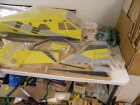
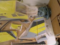
I got home and crashed after that drive so the next day I got it all unboxed
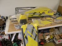
DSCN3102.JPG DSCN3103.JPG DSCN3104.JPG DSCN3105.JPG DSCN3106.JPG DSCN3107.JPG


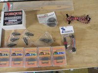
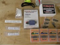
And here is accessories I am going to be putting into the airplane:

Torque 4016/500 Motor
Airboss 80 Amp ESC
6 Savox SV-1250MG High Voltage servos
Savox long servo arms
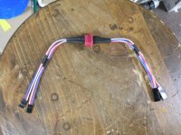
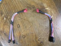
2 Taildragger RC wing harness's
a Two cell lipo battery for the receiver and servos
and a heavy duty switch for the receiver and servos
Falcon 16x7 wood prop
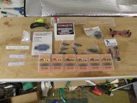
DSCN3108.JPG DSCN3109.JPG DSCN3110.JPG


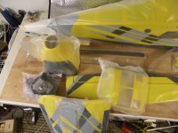
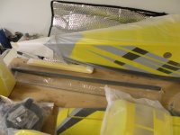
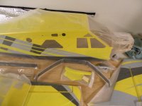
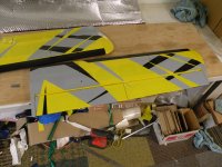
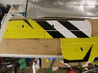
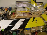
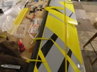
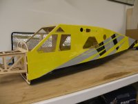
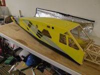
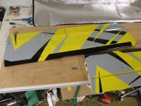
I then unwrapped all the pieces and parts for the airplane. I was very pleased to see that there were virtually no wrinkles in the covering!! Everything was very well packed in the box!!
DSCN3111.JPG DSCN3112.JPG DSCN3113.JPG DSCN3114.JPG DSCN3115.JPG DSCN3116.JPG DSCN3117.JPG


More to come!!
 
Last edited by a moderator:

Bipenut53

150cc
Ok so lets start building!!

First off this airplane is so new that there isn't a final manual published yet, so I am going to wing it. I have built several Extreme Flight airplanes in the past and most of everything looks pretty familiar. I chose to start with the fuselage I cant stand a fuse sliding around on its belly so I started with the main gear.


DSCN3112.JPG


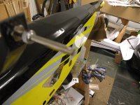
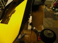
Pretty straight forward. I test fit the gear to their mounting site, tightened all the bolts to suck the blind nuts into position. I removed each bolt one at a time, put red lock tight on each bolt and tightened again.


DSCN3142.JPG


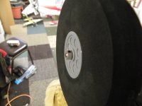
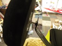
I then installed the axles, typical axles with a large hex on the outside and a nylock nut against a washer on the inside. At this point I installed the inner collar loosely and then the wheel and the outer collar, positioned the wheel where I wanted it, tightened the grub screw to make a mark on the axle and then removed the collars and the wheel. I put flat spots on the axle where the grub screw tightens against the axle for the inner and outer collar with a Dremmel tool and cut off wheel.


DSCN3124.JPG


I then put a little lock tight on the inner grub screw and loosely put in place.


DSCN3122.JPG


Then the wheel and outer collar with lock tight on the grub screw, positioned everything where I liked it and tightened the collars, and repeated for the other side.


DSCN3143.JPG DSCN3144.JPG


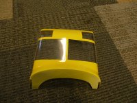
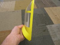
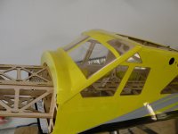
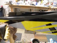
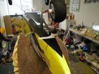
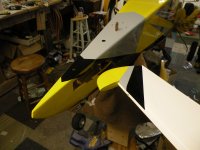
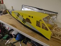
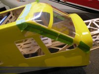
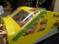
Then it was time to install the windshield, new experience on this family of airplanes, so I went back to my warbird days, I cut the windshield down slowly, little by little with a sharp pair of scissors, until I got it to the shape I wanted and would fit good all the way around.


DSCN3120.JPG DSCN3121.JPG DSCN3122.JPG DSCN3123.JPG


I then used a little 10 minute epoxy, thinned it down very little with alcohol, about the consistency of jelly, I used a disposable brush and coated the edges all the way around and on the top of the F-1 former on the fuselage and taped the windshield in place.


DSCN3124.JPG DSCN3125.JPG


At that point I used thin CA and went around all the motor box all the way around and down to the landing gear box. Trying to get all the joints I could possibly reach.


DSCN3125.JPG DSCN3127.JPG


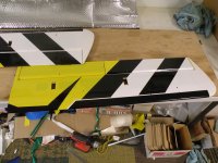
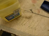
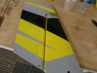
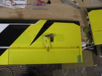
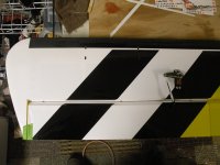
I decided that to give the windshield epoxy a chance to set. I then removed the flaps and ailerons from the wings and removed the pin hinges in preparation for epoxy into place. I use petroleum jelly where the hinges bend to keep them free from epoxy during the gluing process.


DSCN3126.JPG


I then mix up some 30 minute epoxy, I use that carbon rod and spread a little epoxy into each hole and then coat the pin part of the hinges and insert them into the aileron and flap then same process in the wing and insert both assemblies into the proper wing panel and use a little masking tape to hold them neutral so I can clean any excess epoxy that comes out with some alcohol and then let them set aside to cure.


DSCN3127.JPG DSCN3128.JPG


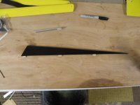
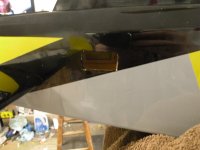
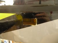
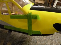
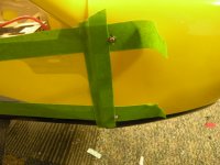
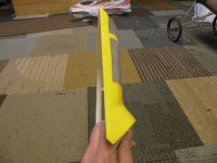
By this time the windshield is dry. I turned my attention to the bottom fin. I found the location of the fin in the bottom of the fuse, cut the slots free from covering and used a sealing iron to open the gaps so the tabs of the fin would fit. I used medium CA and glued it into place.


DSCN3133.JPG DSCN3134.JPG DSCN3135.JPG


That is where I stopped for the night, more to come!!
 
Last edited by a moderator:
Bipenut53

150cc
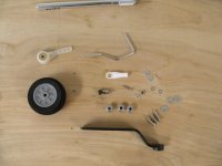
Ok so back at it again. The tail wheel assembly is next.

DSCN3137.JPG


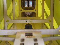
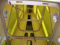
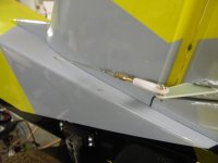
You will notice there is a steering arm included with the tail wheel. The reason for that is the rudder does not extend to the bottom of the fuse like on most common 3D models, so to over come this problem there is a tube inside the fuse that has a steering control rod attached to the rudder servo, through the tube and down to the tail wheel steering arm. Here you see the tube inside the fuse. The second picture shows the steering rid installed


DSCN3132.JPG DSCN3183.JPG


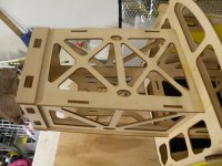
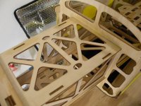
The tail wheel bracket is butted up against the keel that was previously installed, this allows enough rod to reach the rudder servo. Use the tail wheel bracket as a guide for drilling the three holes that attach the bracket to the fuse then use the screws to attach the bracket to the fuse. Remove the screws and bracket and wick a little thin CA into the holes to harden the threads cut in the wood.


DSCN3138.JPG


When the thin CA hardens, attach the bracket. Slide the wheel onto the tailwheel wire and use the collar and grub screw to mark the location to make the flat spot on the axle and tailwheel wire where the collar will go above the bend to act as a bearing.


DSCN3139.JPG


So final assembly of the tail wheel is done, don't forget the lock tight!


DSCN3145.JPG DSCN3148.JPG


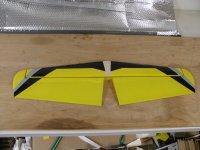
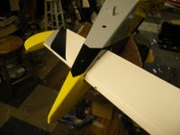
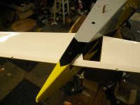
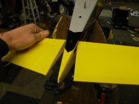
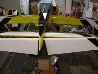
Next is the horizontal stabilizer and elevator assembly. Remove the elevator from the horizontal stab and you will slide that into the opening first. For this I have the fuse in my building cradle. Flip the elevator upside down, slide it into the fuse until the pilots left half is through, slide the elevator forward and flip the elevator over to its proper position.


DSCN3149.JPG DSCN3150.JPG DSCN3151.JPG DSCN3152.JPG DSCN3153.JPG


Then slide the horizontal stab into place.


DSCN3159.JPG


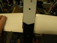
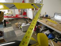
Install the wings, use a tape measure to measure to get the horizontal stab into the correct position, measuring many times until you are satisfied that the stab is square to the fuse and wings. Once satisfied with the position and fit, wick some thin CA into the joint on both sides and top and bottom.


DSCN3156.JPG DSCN3157.JPG


Now its time to hinge the elevator. I used the same process that I used on the ailerons and flaps.


DSCN3154.JPG


Use a little petroleum jelly at the pivot point of the hinges, apply a little 30 minute epoxy into each hole on the stab side and then on the barbs of the hinges, insert into the holes and repeat for the elevator side and insert the elevator onto the hinges. Wipe clean with denatured alcohol and tape into neutral position until cured.


DSCN3161.JPG


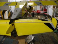
After the hinges have cured, stall fences are installed on the horizontal stab


DSCN3163.JPG DSCN3164.JPG
 
Last edited by a moderator:

Bipenut53

150cc
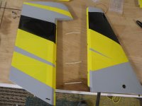
After the horizontal stab is finished, I moved onto the rudder for future use. I will use the same procedure as I did with the wings and elevator hinging process.


DSCN3160.JPG DSCN3162.JPG


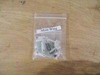
Now its time to install the control horns. As you can see, all the hardware comes in their own labeled bags.


DSCN3155.JPG


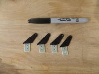
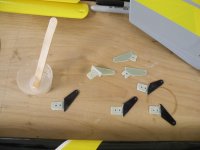
I decided to use SupaTim's idea of "painting" the wing control horns black with the use of a black Sharpie.


DSCN3158.JPG


I sanded the bottoms of the control horns, used 30 minute epoxy to glue in the control horns in the ailerons, flaps, elevator and rudder


DSCN3173.JPG


While the epoxy is curing, I located the hole for the elevator servo on the pilots left side of the fuse. I use a sealing iron on the covering around the hole before cutting the covering from the servo hole. I then cut the hole getting ready for the elevator servo to be mounted.


DSCN3166.JPG


I chose the Savox SV 1250MG servos for this build, one thing about that is that the hole for the servo needs to be made about a quarter inch longer to accommodate them. I used a Dremel tool with the small sanding drum for this job. The key is to try to get the hole just big enough for the servo. I probably should have used a small rotary file in the Dremel but I didn't have one. Here is a photo of the hole just after I got done enlarging the hole just before I cleaned it all up and made it look good but it gives you the idea of how big the hole needs to be.


DSCN3167.JPG


I attached the 24" extension to the servo wire and put a connector lock on it, I stood the fuse on its nose and fed the servo wire into the fuse then mounted the servo. I drilled the holes and put the screws in. I then removed the screws and servo, I used a little thin CA in each screw hole and that hardens the threads in the wood. I did this with every servo in the airplane. I also installed the very cool metal Savox long arms on the servos as I went along.


DSCN3174.JPG


I made the linkage rod that goes from the servo arm to the elevator control horn and installed it. You will have to enlarge the hole in the Savox arm just a little to accommodate the supplied screw. I used lock tight on the nut on both the servo arm and the control horn. You want to use washers on the control horn so the linkage arm does not cut into the fiberglass control horn


DSCN3176.JPG


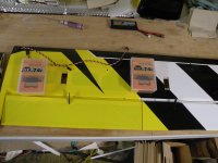
I then began to install the servos into the wings. The aileron servos use a 18" extension, the flaps use a 6" extension and I used connector locks on those as well.


DSCN3175.JPG


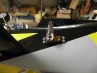
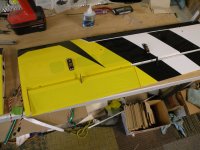
I enlarged the servo holes as needed in the wings and mounted the servos. One thing to note here, the flap servo is very close to the wing tube so when drilling the leading edge holes for the mount screws, make sure you drill straight down because if you drill a little towards the leading edge of the wing you will drill through the outer tube that the carbon fiber wing tube goes into and the servo mount screws will go into the tube and at that point the wing tube will not slide all the way in. I did this on one of my flap servo mount screws and didn't find out until I assembled the wings on the airplane. To correct this problem, I replaced that one servo mount screw with a little shorter screw. But that can be frustrating and it was caused by myself.


DSCN3179.JPG


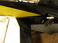
I then built the servo control rods for the flaps and ailerons. I use a piece of masking tape on the end of the flap and the aileron to center the control surfaces so I can mechanically center the servos and linkage on the wing


DSCN3180.JPG DSCN3181.JPG DSCN3182.JPG


After the servos and linkages are installed it is time to put the stall fences on. I used 30 minute epoxy for this. You need to dry fit the fences to the wing before gluing as the tabs that go into the wing are just a little too large for the holes in the wings.


DSCN3184.JPG


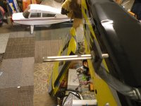
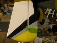
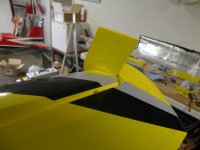
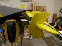
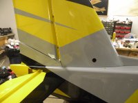
It is now time to install the vertical stabilizer and rudder assembly. There is a smaller carbon fiber rod that fits in the bottom of the vertical stab. There Is a bolt and washer in the bag that holds the rudder hardware. There is also a wedge piece that fits under the rudder and gets installed at the same time. Use lock tight on the bolt you insert through the hole in the vertical stab to hold it to the tab on the fuse. Then position the wedge piece in place, it has a pin that fits into the fuse and wick a little thin CA into the seam to hold it in place.


DSCN3185.JPG
 
Last edited by a moderator:

Bipenut53

150cc
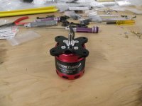
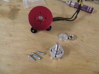
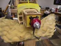
It is time to get the Torque motor ready to install on the firewall. Locate the collar that goes on the shaft of the motor and install it on the shaft and use lock tight on the grub screw that holds the collar in place, and then put the motor mount in place and use lock tight on the bolts holing the mount to the motor.


DSCN3186.JPG


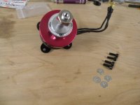
Put lock tight on the bolts that hold the prop hub to the motor. Then get the assembly ready to mount to the firewall by finding the provided motor mount bolts and washers.


DSCN3187.JPG DSCN3188.JPG


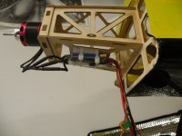
Attach the motor to the firewall with the wires pointed down. Again make sure you use lock tight on the motor mount bolts.


DSCN3189.JPG


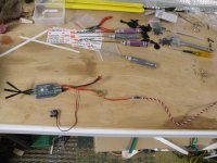
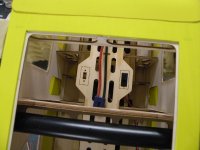
Get the ESC ready to attach to the bottom of the motor box. You will need a 12" extension on the throttle wire to reach the receiver. I used a connector lock on that as well.


DSCN3190.JPG


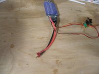
I am using a 2 cell lipo battery for the receiver and servos. The reason for that is the Airboss 80 amp ESC is not designed to be used with 6 servos so you would either need to use a separate BEC or a separate battery. I chose the battery option because my servos are rated for 7.4 volts. So to keep the ESC from sending even more voltage to the receiver and burning it up, you need to clip the red wire. I chose to do this in the extension going to the receiver so if there was a problem with the ESC it would not be altered.


DSCN3191.JPG


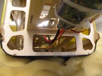
The other thing that needs to be done is you either need to build an extension for the battery to the ESC or solder on wire to extend it far enough to reach the battery. I use EC-5 connectors so I chose to cut the Deans connector off the ESC and solder on silicone wire and put my EC-5 connector on. I also used some scrap foam and wire tied the ESC to the bottom of the motor box.


DSCN3192.JPG DSCN3193.JPG DSCN3194.JPG DSCN3195.JPG


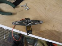
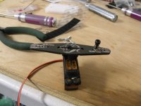
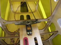
Time to get the rudder servo ready. I used the Savox 4" full arm. You need to put the tail wheel steering connector on the rudder arm. It goes on the pilots left side. Lock tight the nut on the bottom of the connector. The picture you see has sawdust on the servo because I had already installed the servo and removed it to put thin CA on the threads.


DSCN3196.JPG DSCN3197.JPG DSCN3200.JPG


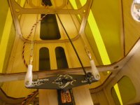
Time to do the pull pull cables on, I really don't like making these wires but it went pretty smooth and un eventful. The way I did it was before I mounted the rudder servo for the last time, I strung one wire in from the tail where the holes are for them. So for the wire that goes in on the pilots right needs to be hooked up to the servo on the pilots left side of the servo. Loop the wire through the connector and run it through the aluminum collar and then loop it through again and crimp it. Then do it for the other side. Mount the servo in its place.


DSCN3204.JPG


Then I use masking tape on the counter balance of the rudder to keep it neutral. I turn on the power to the servo to keep it centered while tensioning the wire and finishing the connection at the rudder control horns.


DSCN3205.JPG


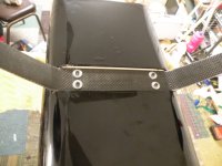
In the rudder servo mount pictures you see a red connector. This is a harness for the right wing that makes it easy for servo connections and they only fit together one direction. One half of the connector goes on the airplane and gets connected to the receiver and the other half hooks up to the wing, flap and aileron servo wires. [MENTION=335]SupaTim[/MENTION] sells them as well and it makes connecting the wing servo wires a breeze!!!


DSCN3198.JPG DSCN3199.JPG


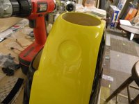
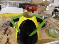
So now its time to get the cowl ready. The turbo exhaust stacks need to be glued on. First scuff up the indentation in the cowl and the fiberglass exhaust stacks. Then use Welders glue and put them in place and then tape to hold them on while the glue cures.


DSCN3201.JPG DSCN3202.JPG DSCN3203.JPG


Once the Welders glue has cured holding the exhaust stacks on the cowl its time to mount the cowl. Using masking tape, center it on the mounting tabs where the cowl mounts to and run it back to the cabin area. Mark the center of the mounting tab with a pen, pull the tape back and slide the cowl on and put the tape on the cowl to hold it in place with the backing plate of the spinner as a guide for spacing.


DSCN3208.JPG


Tape the cowl in place and drill the mount holes for the cowl.


DSCN3206.JPG DSCN3207.JPG


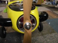
Remove the screws, tape and put some thin CA on the threads and mount the cowl and install the prop and spinner.


DSCN3209.JPG DSCN3210.JPG


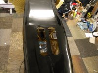
The final step for me is put in the cooling holes. They are located right in front of the keel. I used a sealing iron and sealed the covering down around the holes, removed the covering from the holes and ran the sealing iron around it again.


DSCN3211.JPG


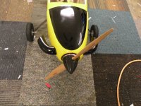
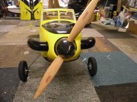
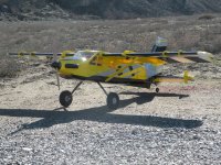
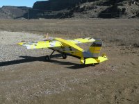
And here is the completed airplane just before the maiden.


DSCN3212.JPG DSCN3213.JPG DSCN3214.JPG


Stay tuned for flight video!!
 
Last edited by a moderator:
Bipenut53

150cc
Here is the flight video of my Turbo Bushmaster. One thing I must say, the camera we used is not a video camera so the quality of the video is fairly poor and looks better in the small window. Thank you to [MENTION=4379]cam4569[/MENTION] for his time in shooting the video.


[video=youtube;zXw3D4zzSfI]https://www.youtube.com/watch?v=zXw3D4zzSfI[/video]
 
Last edited by a moderator:
Bipenut53

150cc
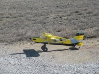
The review of the Legacy Aviation Turbo Bushmaster. This airplane is everything it is billed to be and more. The build was detailed and a lot to pay attention to. The quality of the kit is what you come to expect from an Extreme Flight airplane kit. Straight forward enough that I could build it without a build manual. [MENTION=335]SupaTim[/MENTION] provides excellent support and customer service. I would definitely purchase another airplane from him, and probably will. I used 6 cell 5000 mah battery for flight and got 7 minute flight times. This airplane came out at 8 pounds even ready to fly, and that includes the extra 2 cell lipo I am using for the receiver and servos, very impressed. I do think I am going to experiment with a few prop combinations to see what I like best for my kind of performance. So on the maiden, I had to give it 4 clicks up trim, two clicks of left rudder and two clicks or right aileron. Not much in the way of trim so I was pleased. The maiden flight consisted of a few loops, rolls and gentle flying, I also tried out the flaps and they slow the airplane down really well. Flaps on 50% on take off gets you in the air in under 10 feet!! After maiden flight I checked the airplane over for anything unusual, all looked good!! So second and third flights were more aggressive. This airplane does not fly like your normal 3D airplane, it is going to take some time to get used to. That being said, this is one of those airplanes that when you get it in the air you have an instant smile, and start giggling like a school girl. When you want to do a flat spin you need 50% flaps, stall it, kick in rudder and a little up elevator and throttle and it looks like it is spinning pushing the tail backwards! It is truly something to see. It will flip on command, stall it, full up elevator, pop some throttle on and bang it flips. I know I am going to have a blast with this thing!!! You can knife edge all day long. If I was pressed to find a con on this airplane would be set up time, normal wing install but you do need to put the wing struts on, and that is getting picky. I do like this airplane!! If I were to describe it in one word that would be AWESOME!!!!

Feel free to ask anything about the build and flying of this airplane although I am still learning how this airplane flys.
 
Last edited by a moderator:
3dmike

640cc Uber Pimp
Woo Hoo! Looking forward to this build bipenut! Looks like a well built well thought out design!
 
Top