• If you are new to GiantScaleNews.com, please register, introduce yourself, and make yourself at home.

    We're 1st in Giant Scale RC because we've got the best membership on the internet! Take a look around and don't forget to register to get all of the benefits of GSN membership!

    Welcome!
  • Unless you are a paid advertiser NO more posting advertisement in the individual vendor forums. You may post in the Manufacturer's Announcements section only but only ONCE a month unless your a paid advertiser.

Twisted Hobbys / RC Factory's Brand New 36" EPP FLASH NG, "Official Build Thread"

AKfreak

150cc
15221226567_f2d9e66ae0_b.jpg

Twisted Hobbys / RC Factory's Brand New 36" EPP FLASH NG, "Official Build Thread"

This is the, "Official Build Thread" or the Twisted Hobbys / RC Factory's Brand New 36" EPP FLASH NG. All I can say is that I super excited to share this build with you folks, but before I start the build, I want to give a little of back story. As many of you know, I am a huge Twisted fan. I have built and own many TH planes, and I just love them. All of the planes I have owned each have a different personality, but share the one common trait,..... quality!

A week ago I was asked if I was interested in doing a build of a brand new line of planes from RC Factory. In case you don't know, RC factory is the place that brings the visions and projects of Twisted Hobbys to life. Well, I bet you guessed it by now, I said heck yes I would be interested in building the new design. This new design (36" inches) is bigger than the standard sized (32" inch) offerings from TH, but a little smaller than the new big dogs (39" inches) they just started offering not so long ago.

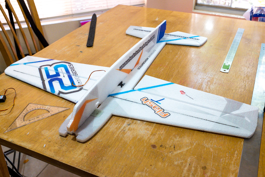
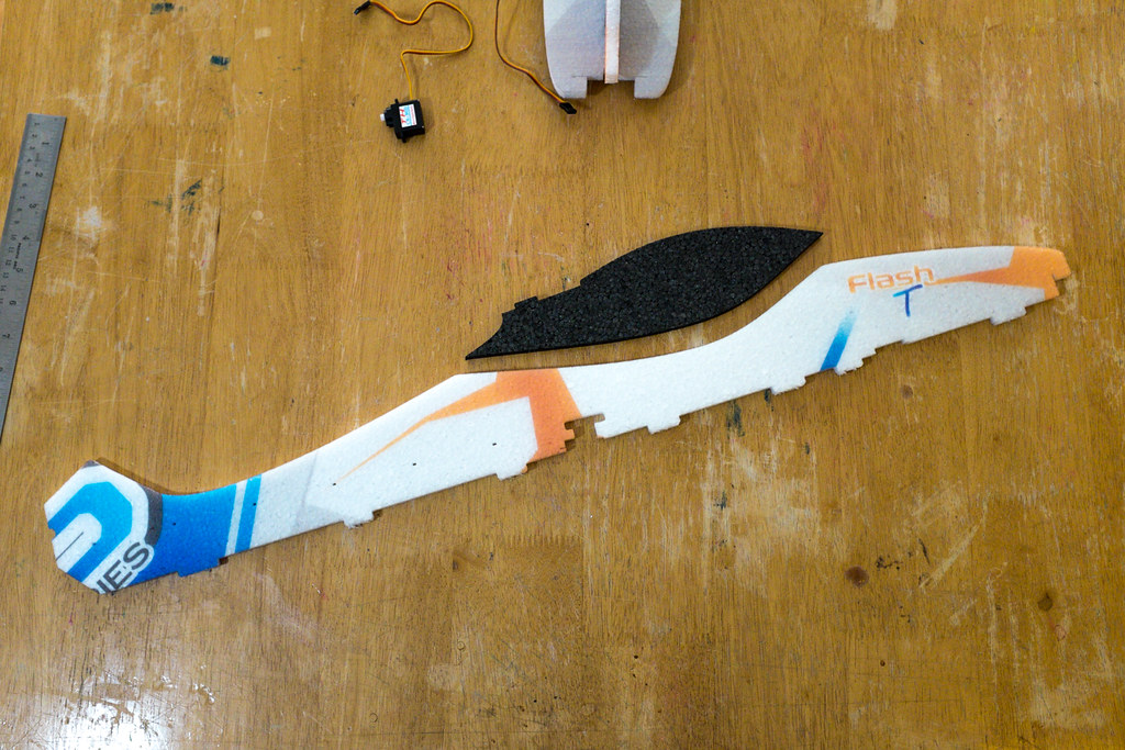
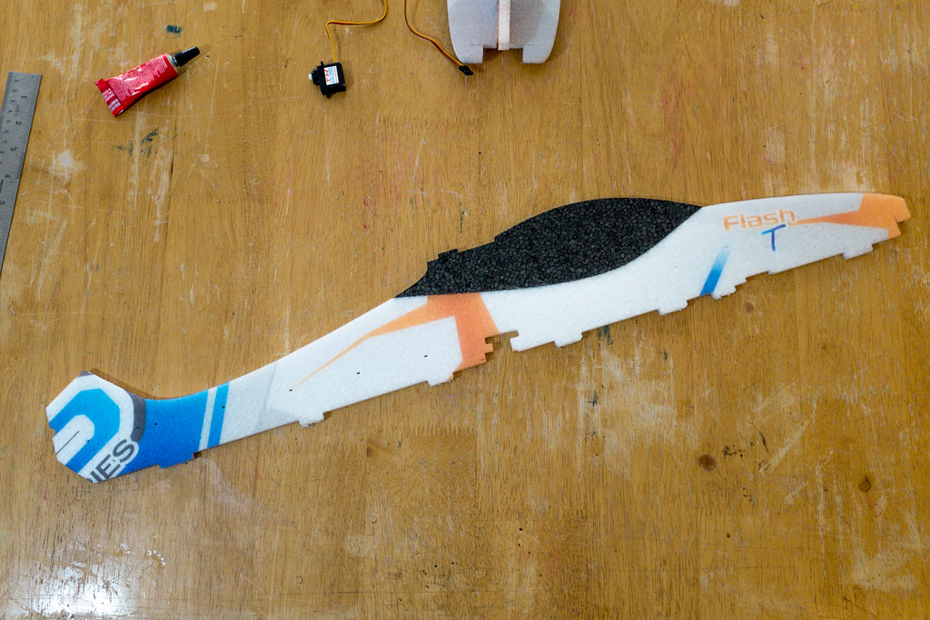
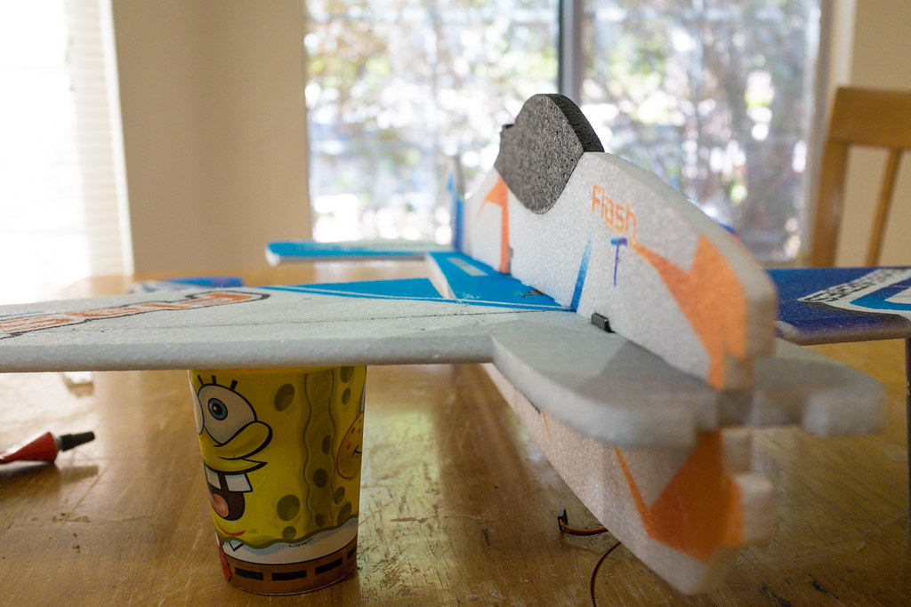
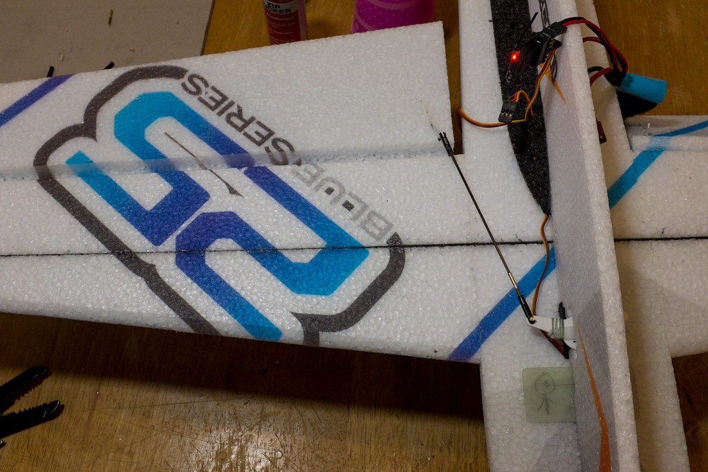
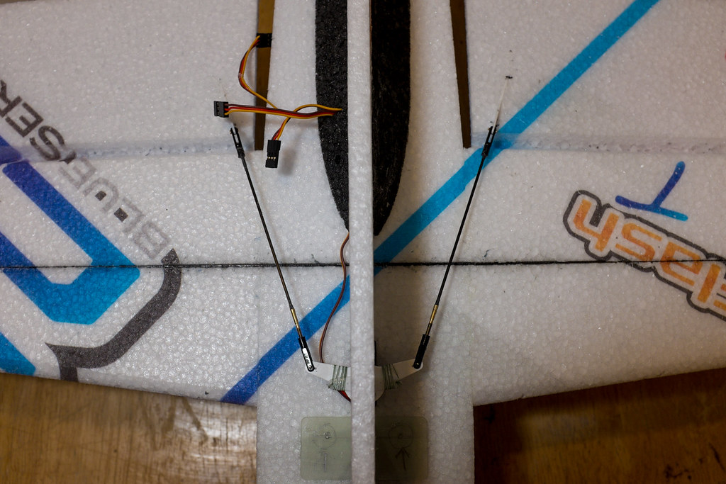
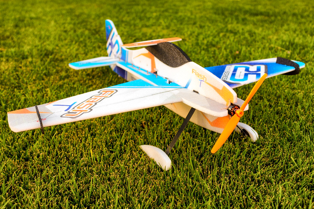
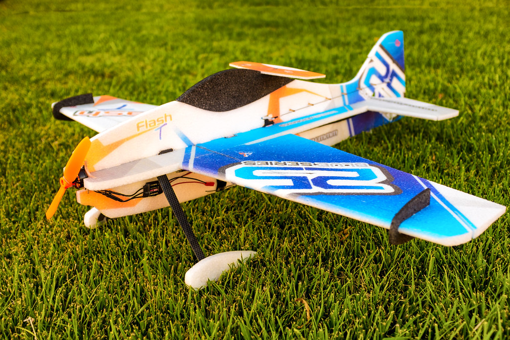
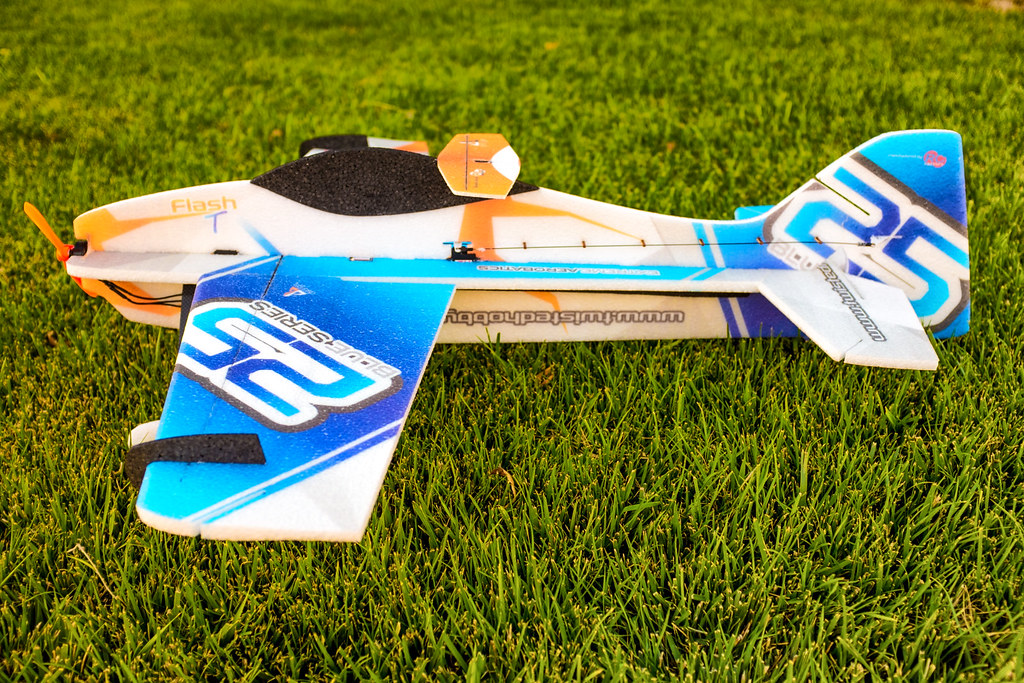
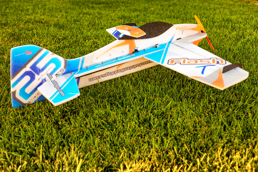
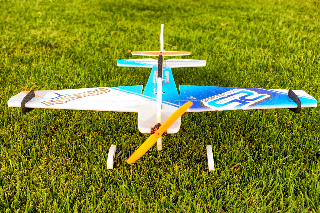
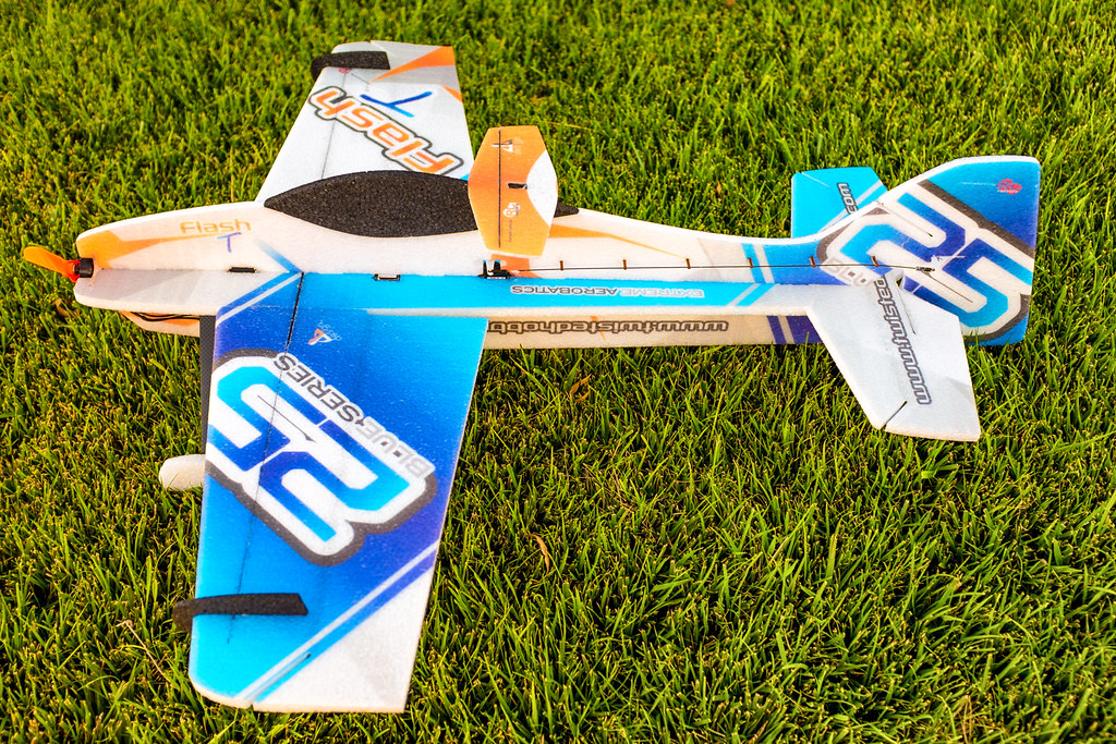
The Flash NG also knows as the Flash "T" should prove to be a great sized foamine to master 3D. At 36" inches it should do a little better in the wind than the 32" planes, but fit much easier than the new 39" planes. Another feature that sets this model apart is the fact it has Air foiled leading edges. That is to say the leading edge of the wings, and the horizontal stabilizer is radiused. Also the color is simply beautiful, and it's called. "the blue series".

Take a few minutes and watch this video below, as I offer to the world for the first time the all new, " 36" EPP FLASH NG"
[video=youtube_share;aJLkUfY52Qs]http://youtu.be/aJLkUfY52Qs?list=UUCa6sk3mAf6dT4wY9TYaNNg[/video]


I want to address how I am going to convey information in this build thread. Many people like written words and photos, while others prefer video. I like both depending on what platform I am on (PC, Phone or Tablet). So with that said, I will be offering the information in all forms. Remember some of the information will be repetitive, I just wanted you to know why. Any yeah, it's more work to present information in this way, but you guys are worth the effort ;)


Lets Begin.

15251246976_43af76d536_b.jpg

15087496689_bc6b38ae52_b.jpg

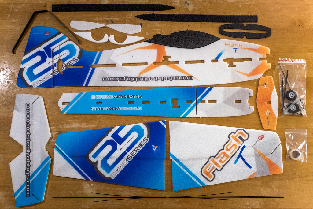
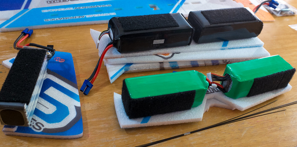
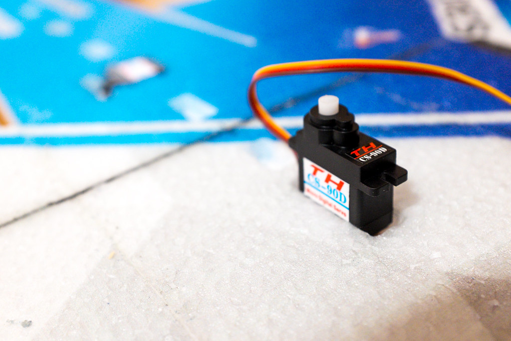
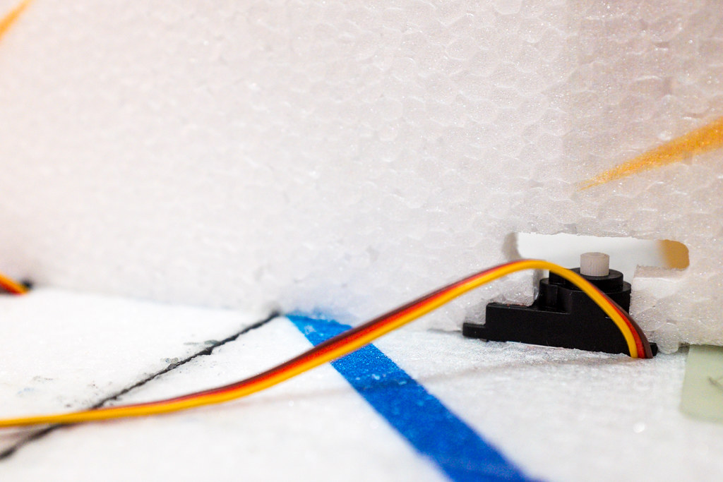
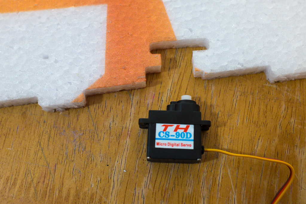
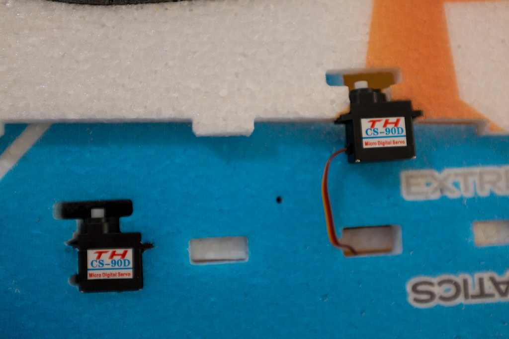
After you have gone through and inventoried the parts to make sure you have everything to build your new plane, the first step is to weigh down all of the control surfaces for 24-48 hours. This will help deal with any memory issues that the foam retains at the hinge points. This memory will cause the servos to work too hard (and they will burn up). Also you wont achieve a full or equal throws which can cause major performance issues. You got the best model, you need to insure it will fly as it was intended.

Video Quick Tip
[video=youtube_share;t50fMxICiWs]http://youtu.be/t50fMxICiWs?list=UUCa6sk3mAf6dT4wY9TYaNNg[/video]

Tools You May Need
15261788326_7d97acd778_b.jpg

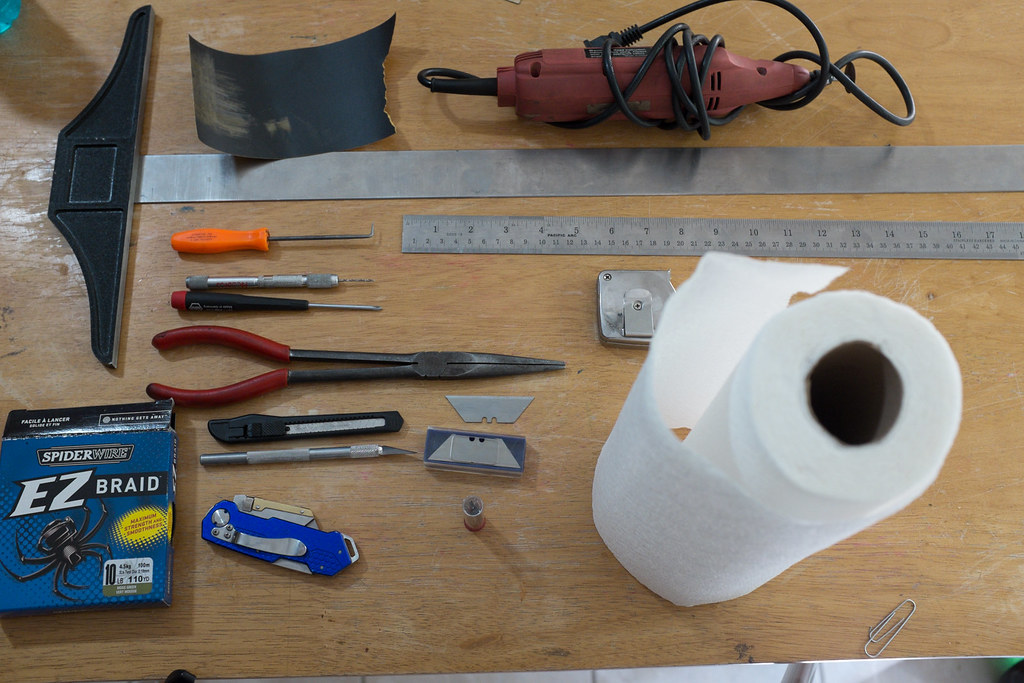
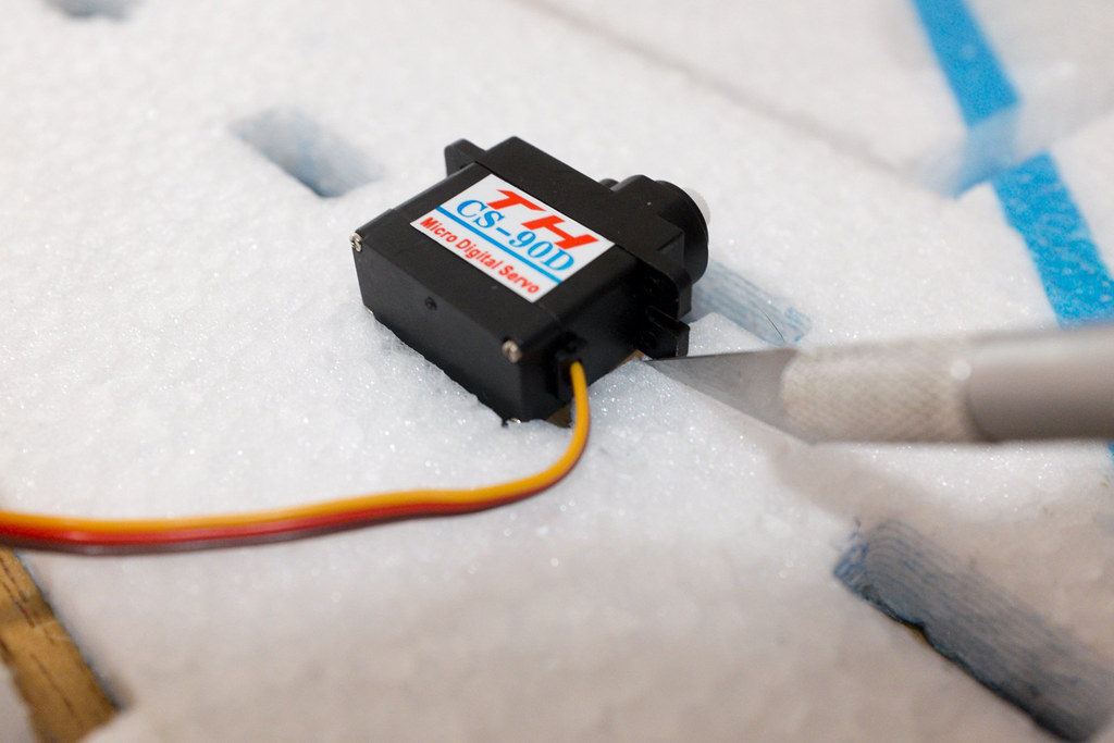
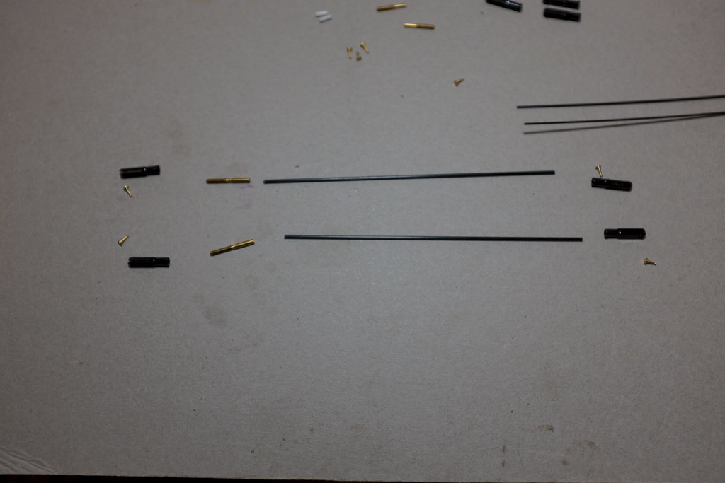
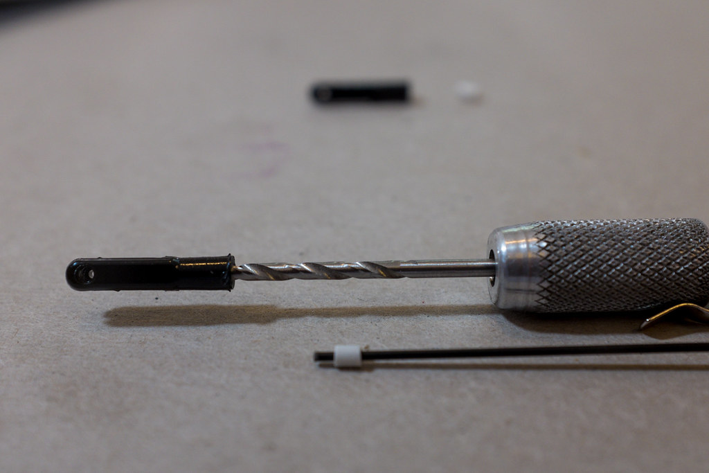
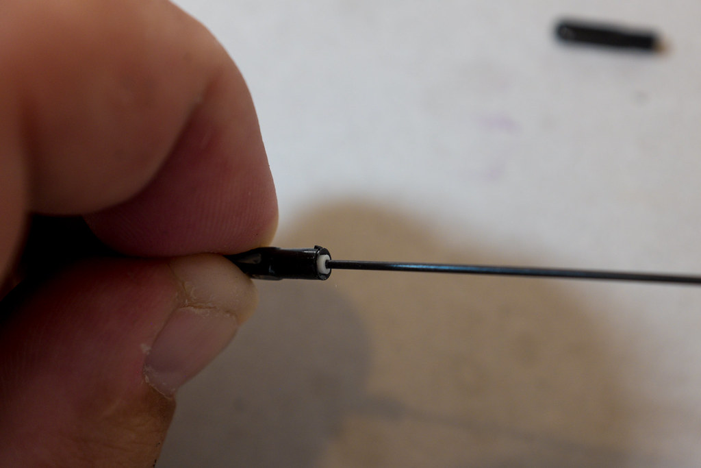
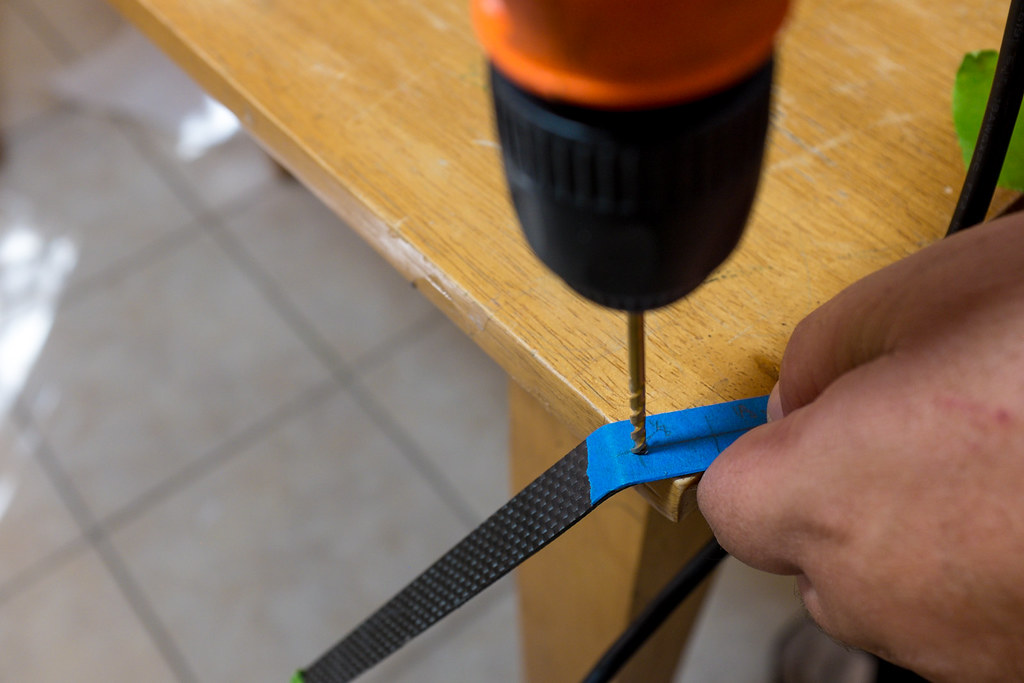
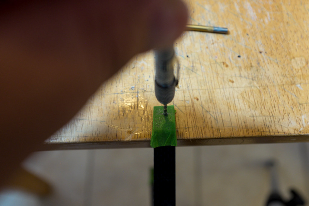
Before you build the plane, you may want to collect all the tools you will need to complete the job. You will need a Sharp Razor Knife of some sort. You will also need a drill, some sand paper, some pliers, a long metal straight edge, a pick, a tape measure, and possibly a dremel tool to cut the carbon fiber control rods.
[video=youtube_share;N4_zAPAnxLc]http://youtu.be/N4_zAPAnxLc[/video]
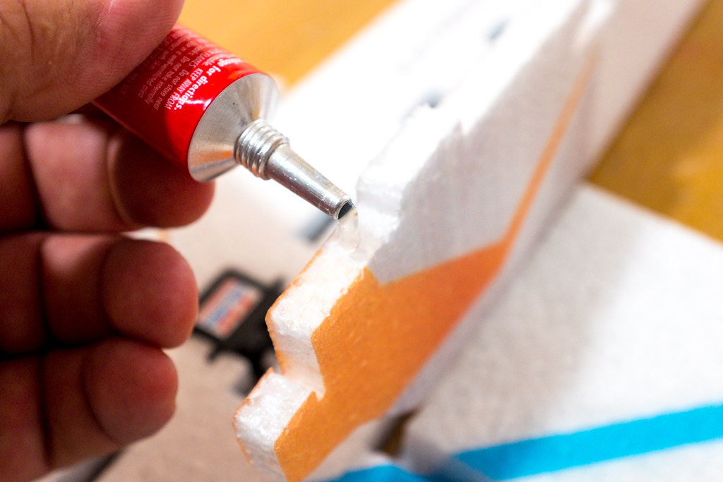
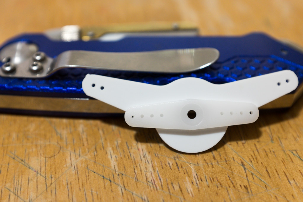
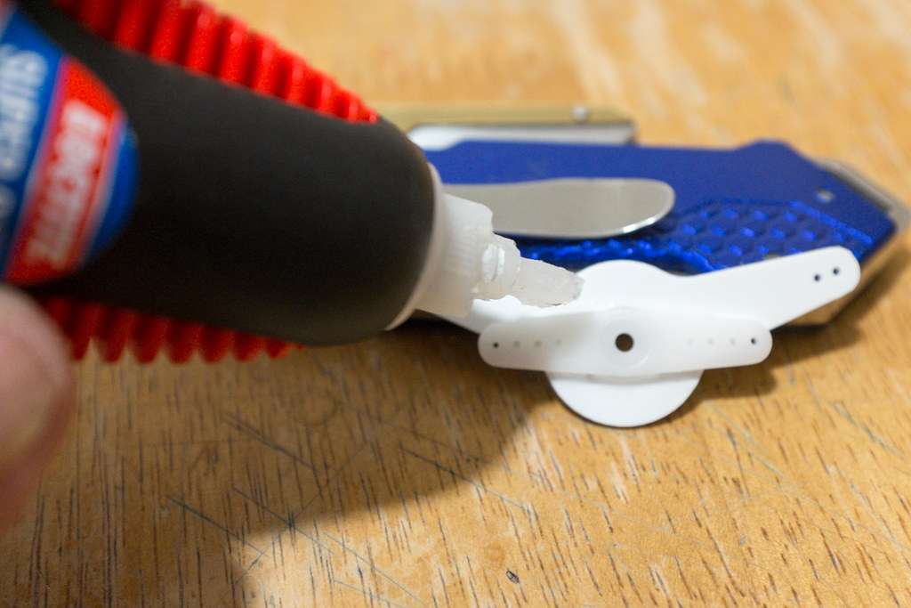
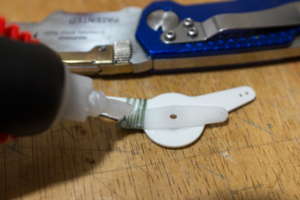
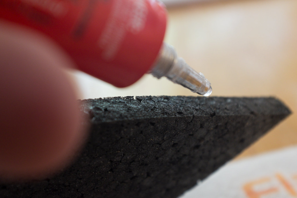
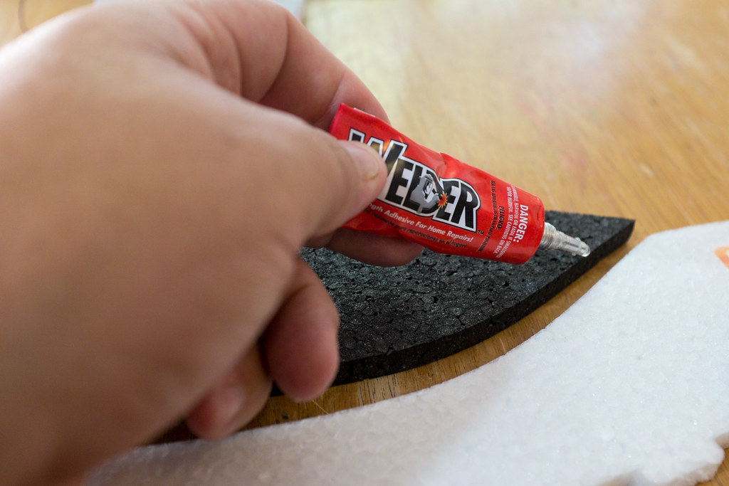
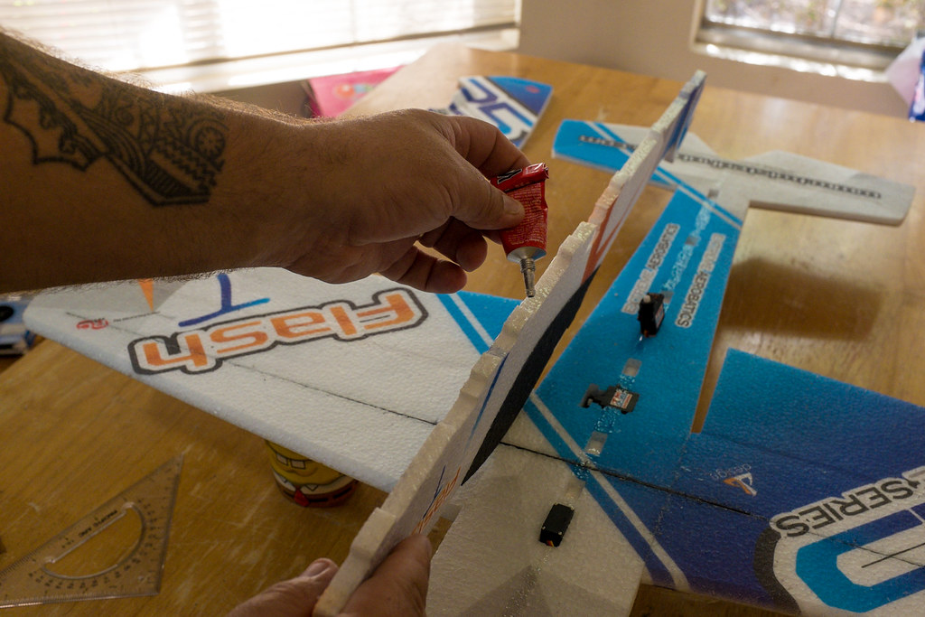
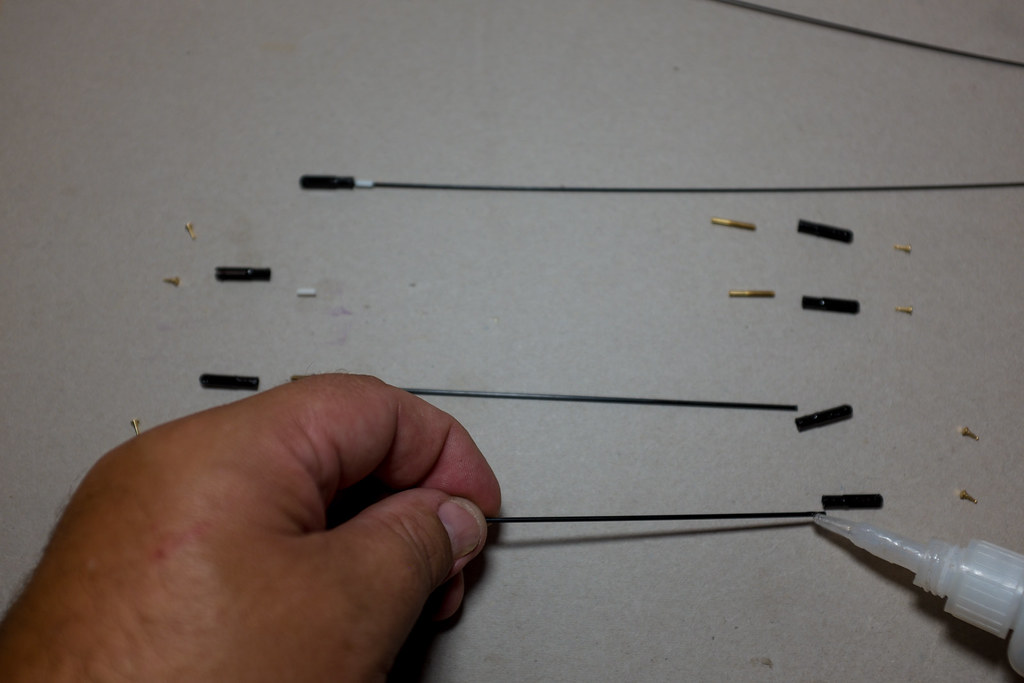
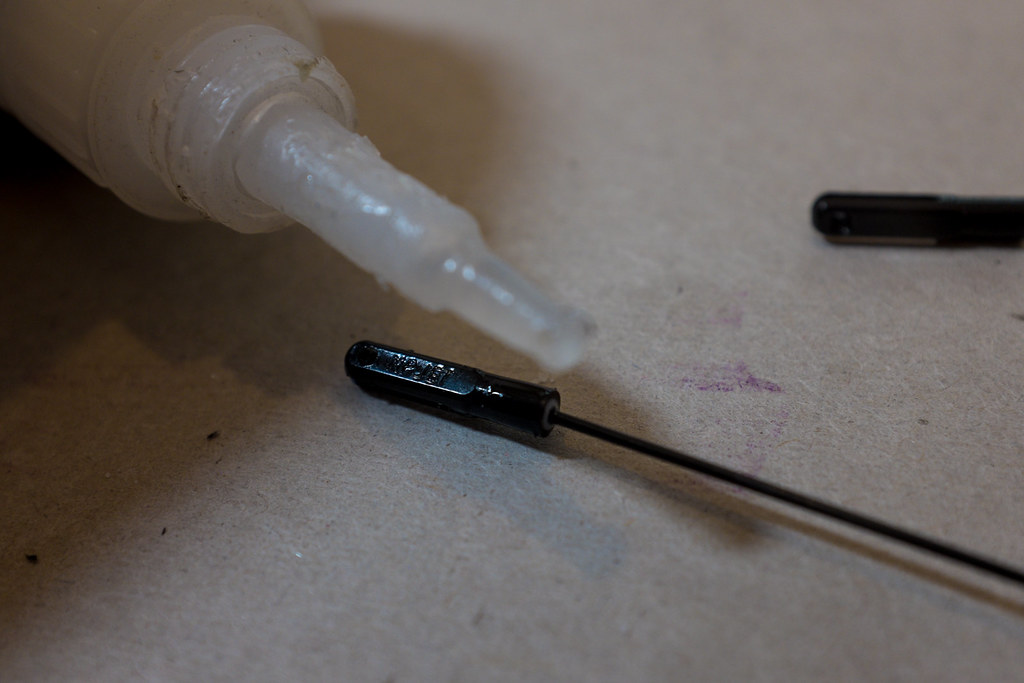
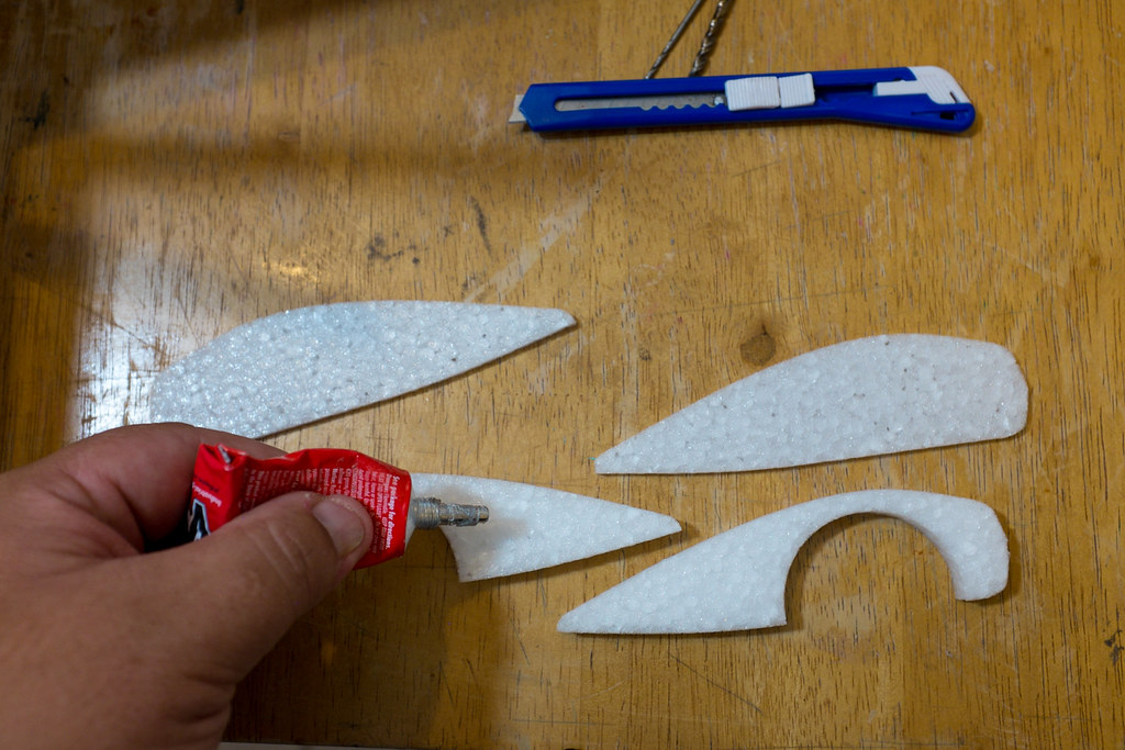
"Welders Glue"
15262191376_3f3d8e7cd2_b.jpg


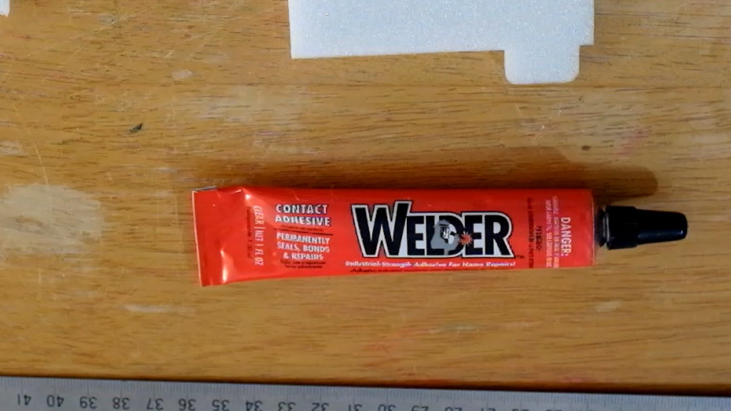
The Glue we will be using to build this plane is called, "Welders". You can get it when you buy your kit from Twisted Hobbys. This glue is contact cement and works pretty good on EPP foam. Welders is kind of hard to find at the hardware store, and for $5 bucks, like I said you get two tubes from Twisted. There are several ways you will have to use this type of glue. One way is the recommended way, as a contact cement. You apply glue to the both surfaces that are going to be bonded. Press them together, then pull them apart, then let them dry for 5 to 10 mins. Once this stuff dries, then it is pressed back together, it stays stuck very well. However there are times when you need to shift parts around, this is when you need to use the, Wet" method of working with this glue. Welders can also be used to make control surface hinges. Welders is pretty neat stuff, and it has been used for a long time to build foam models.
[video=youtube_share;fl6yBs_IfR4]http://youtu.be/fl6yBs_IfR4[/video]

Setting Up, Cutting & Insalling The Wooden Spar Strip

15286965761_7a3838c71e_b.jpg

15103554517_7e5b8fe6f9_b.jpg

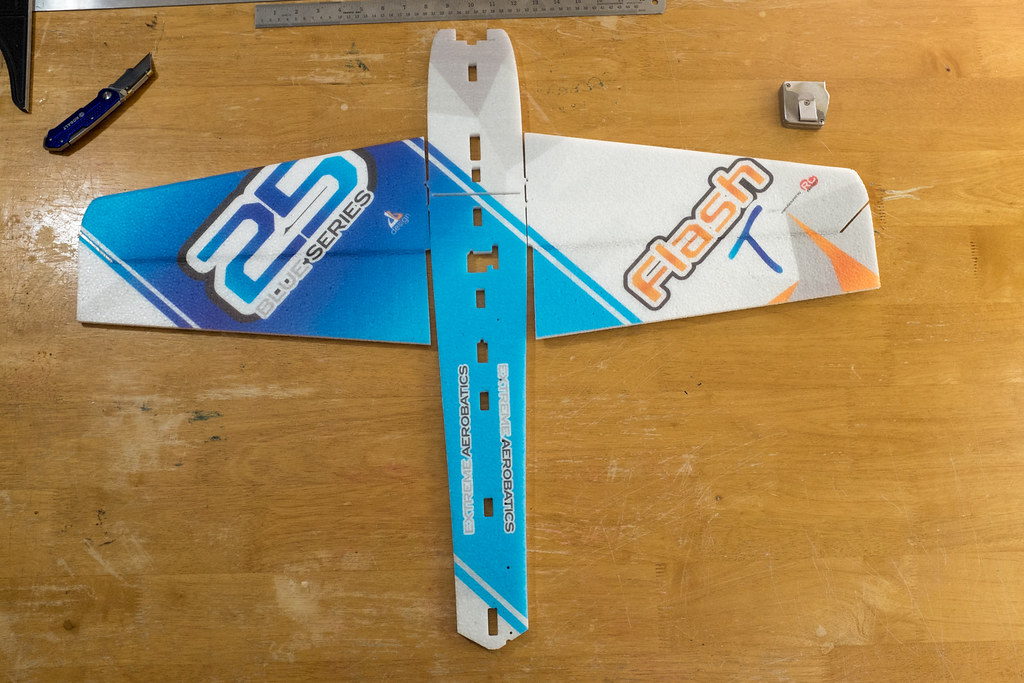
When you put you wings and Horizontal fuse on the build table, you will quickly realize that the Wings and the Fuse registering table don't line up. The first time I built this type of model from TH/RCF, I was scratching my head because I didn't realize you need to cut the horizontal fuselage in to two pieces. (I hate directions ;))

15289721112_e19013229c_b.jpg

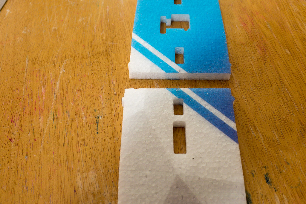
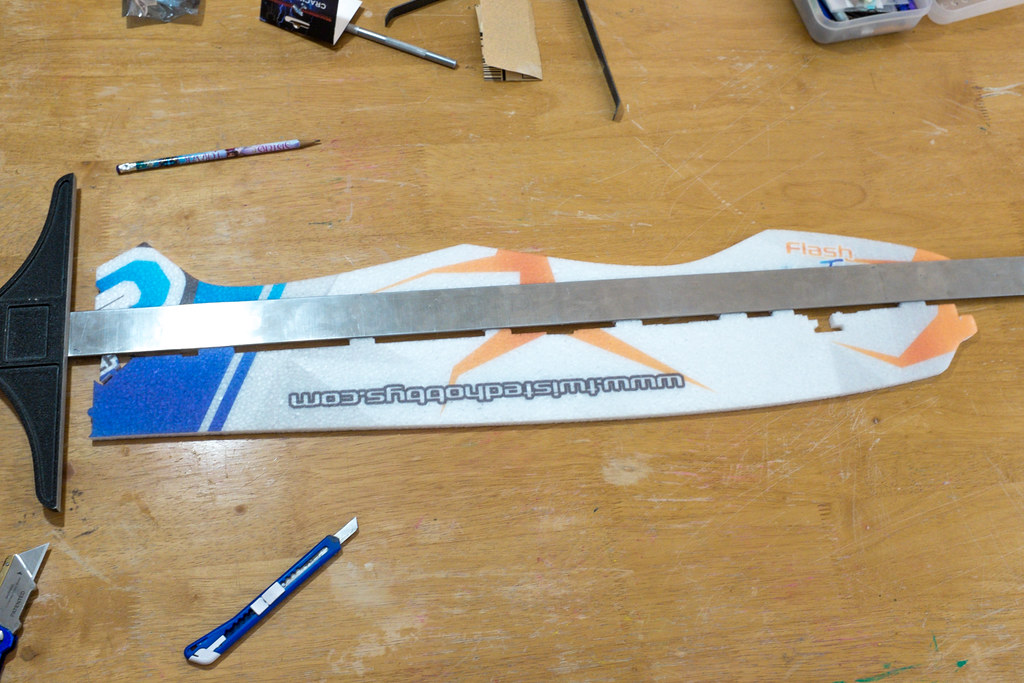
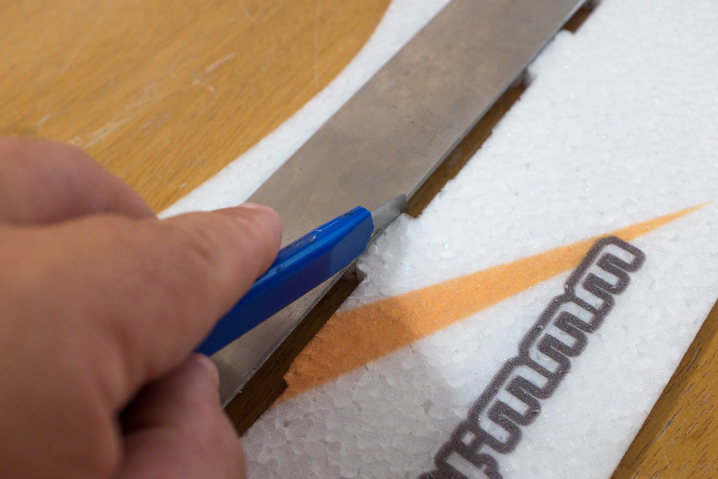
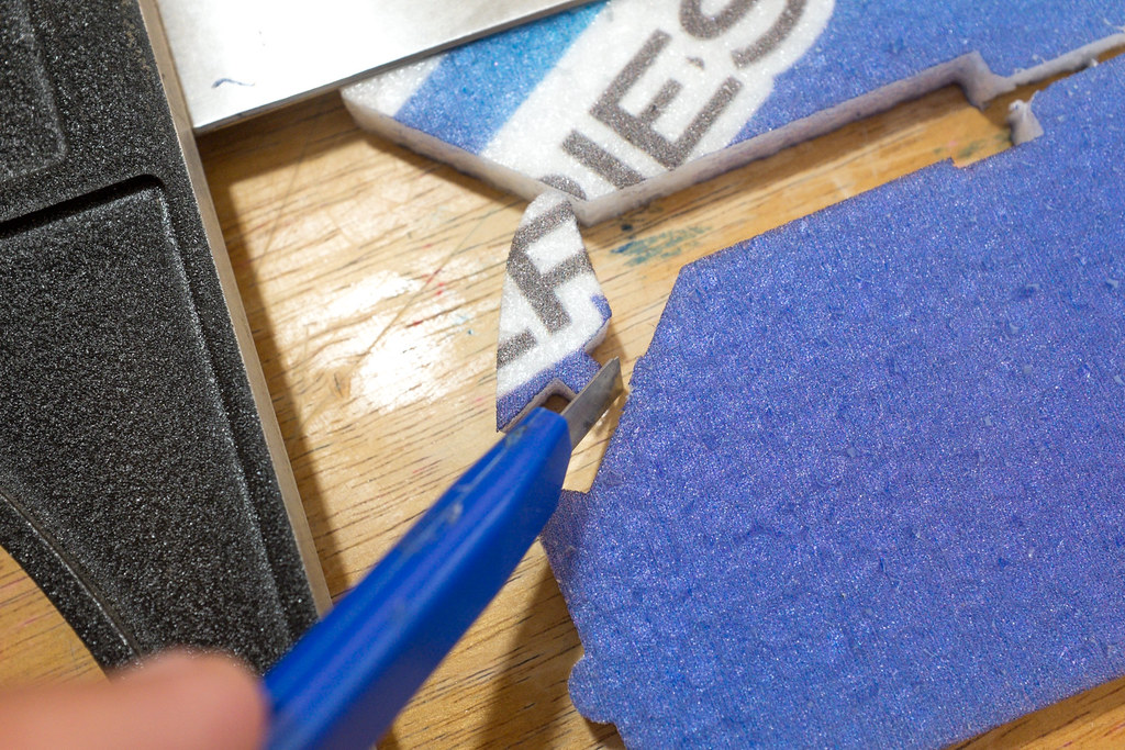
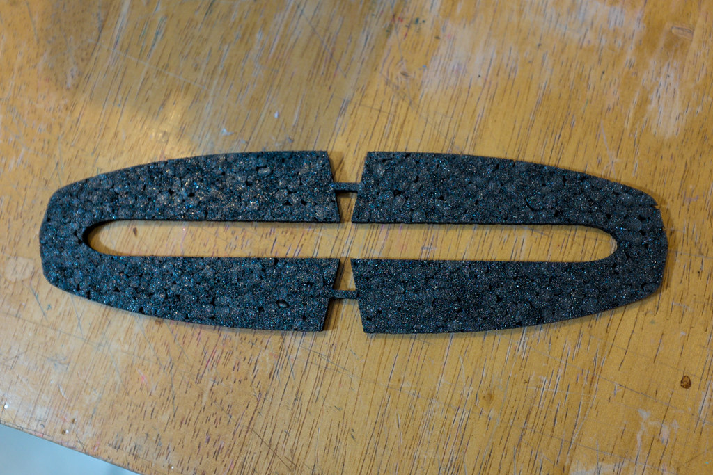
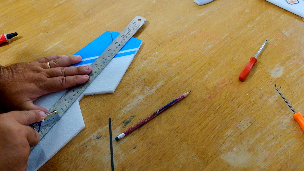
So, grab your metal strait edge and a sharp razor knife and split the horizontail fuse into to pieces, then use the straight edge to trim off the resulting tabs, so you end up with a front and back horizontal fuselage sections that will butt flush against each other.

15290123565_8fbe661cd6_b.jpg

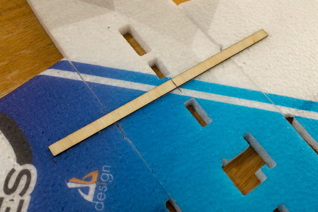
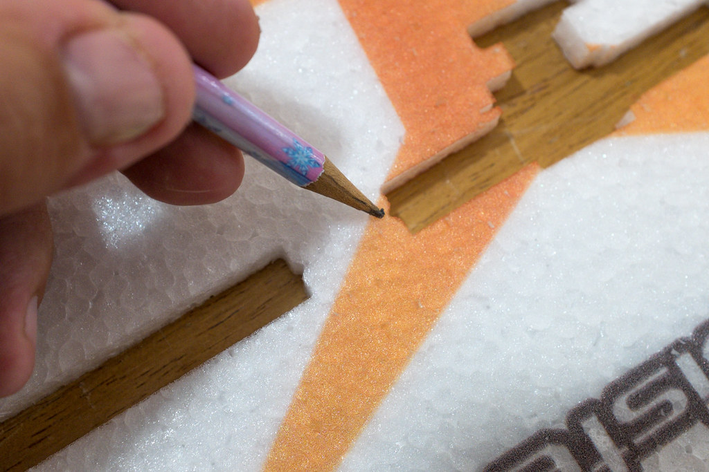
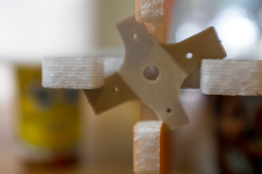
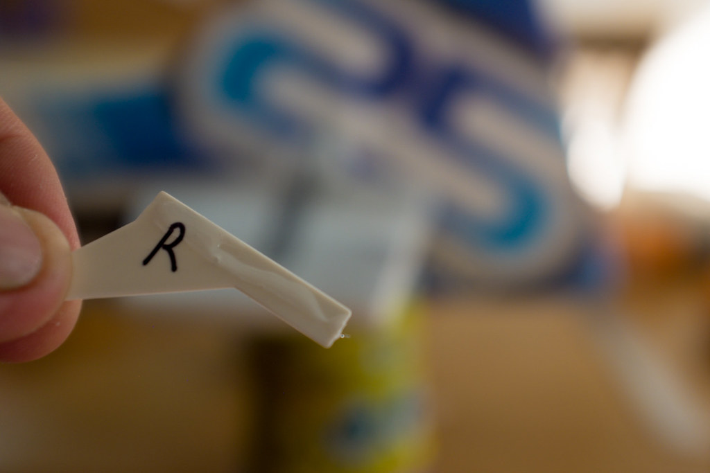
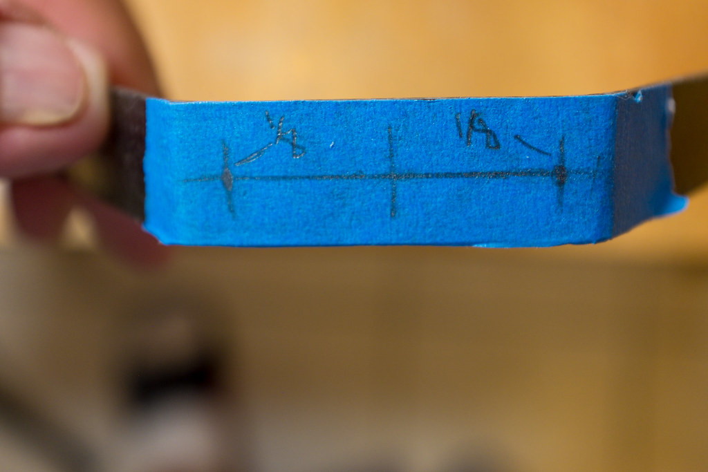
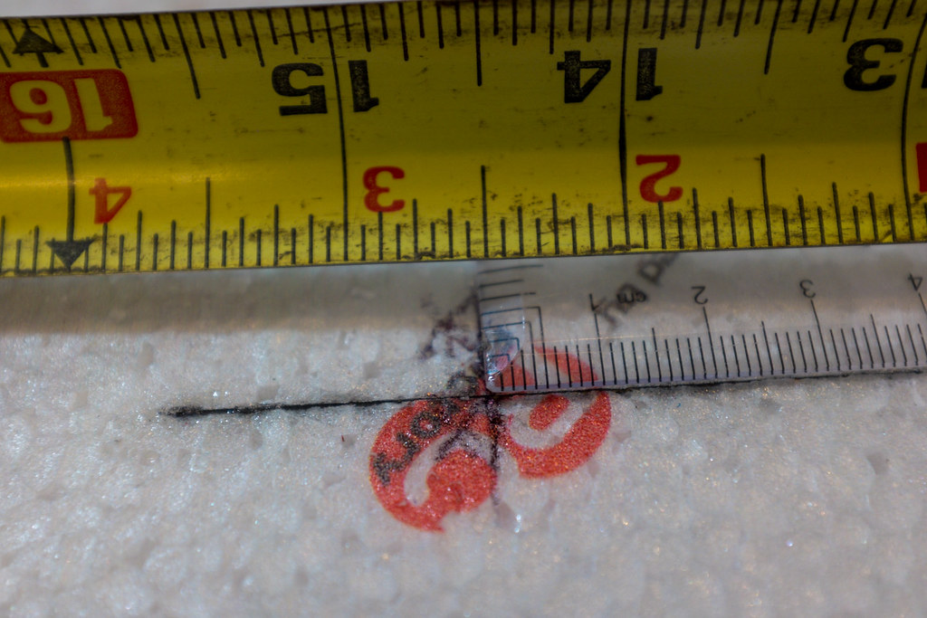
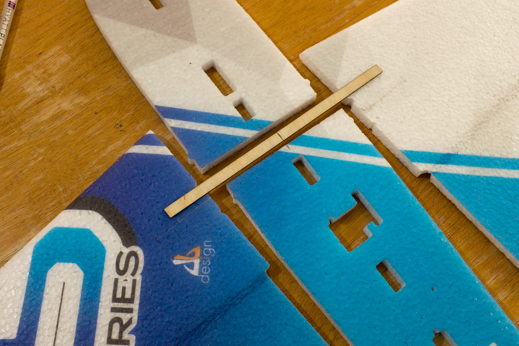
Now you need to fit the wings and horizontal fuse parts together, and grab the wooden spar strip. On the strip,you need to measure and mark center. Also mark center on the horizontal fuse section. Then line up the mark on the spar strip with the mark on the horizontal fuse. In doing so, you have just registered the wooden spar.

15286964541_9efbc62121_b.jpg

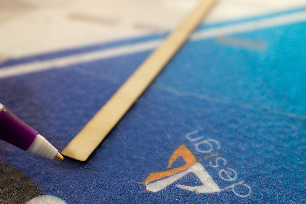
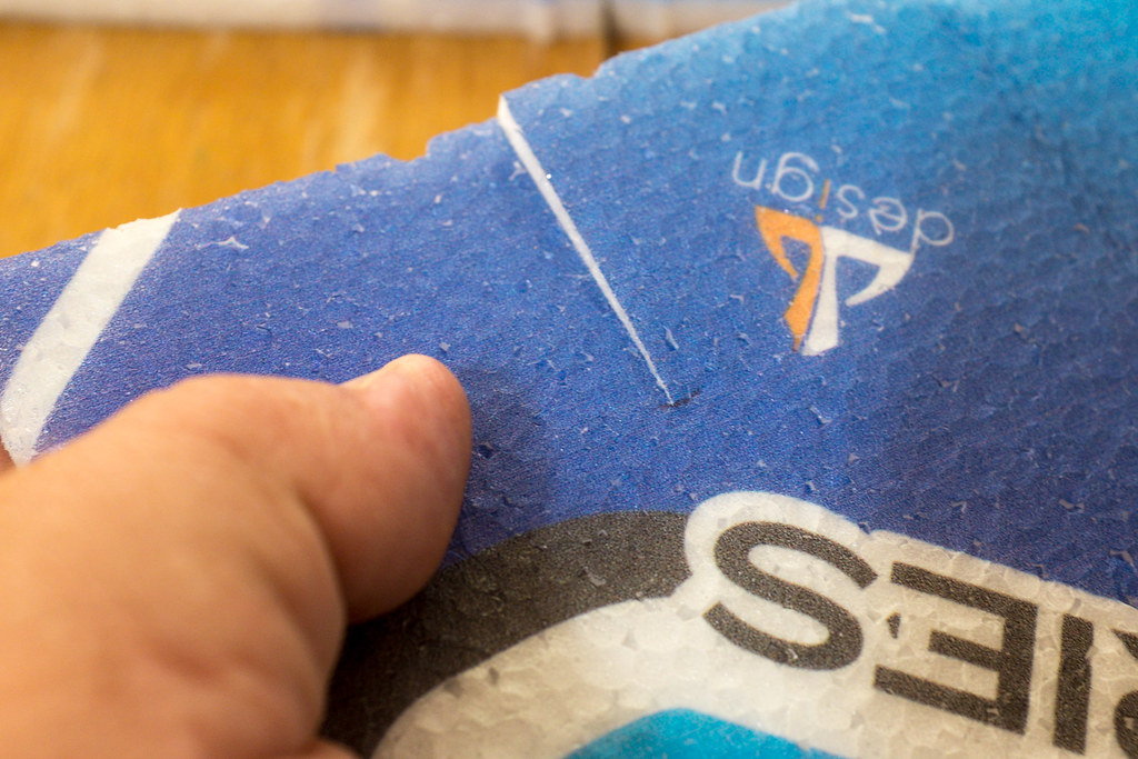
Now you need to make marks on the outside of the spar. Make the marks on both the left and right wing, these marks will serve as the stopping point when you make your cuts to install the spar to the wings.

15103538398_c7f956c55b_b.jpg

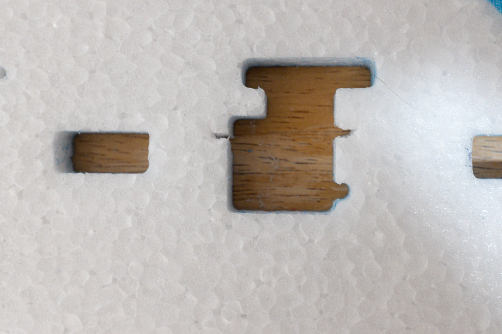
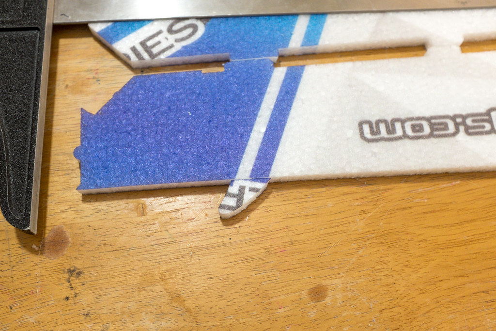
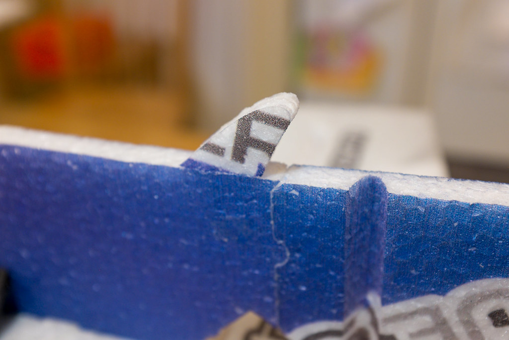
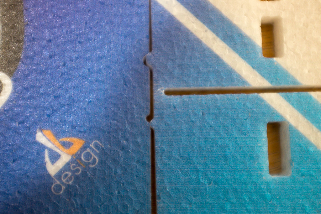
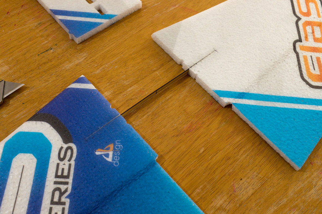
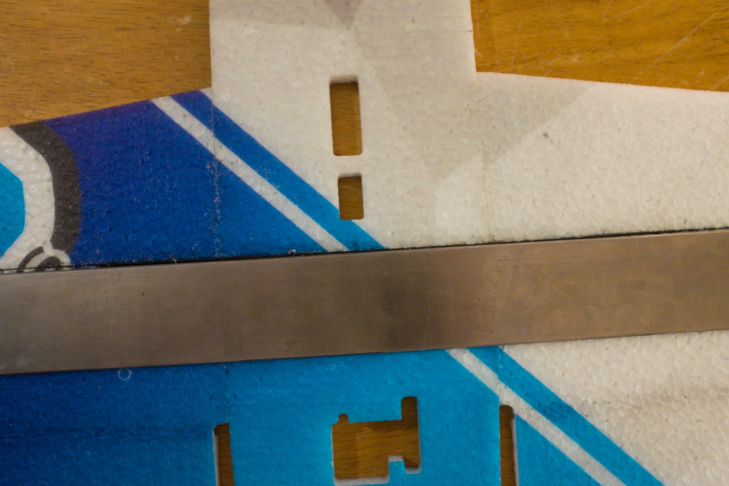
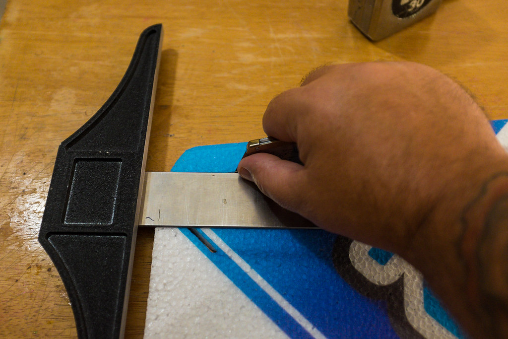
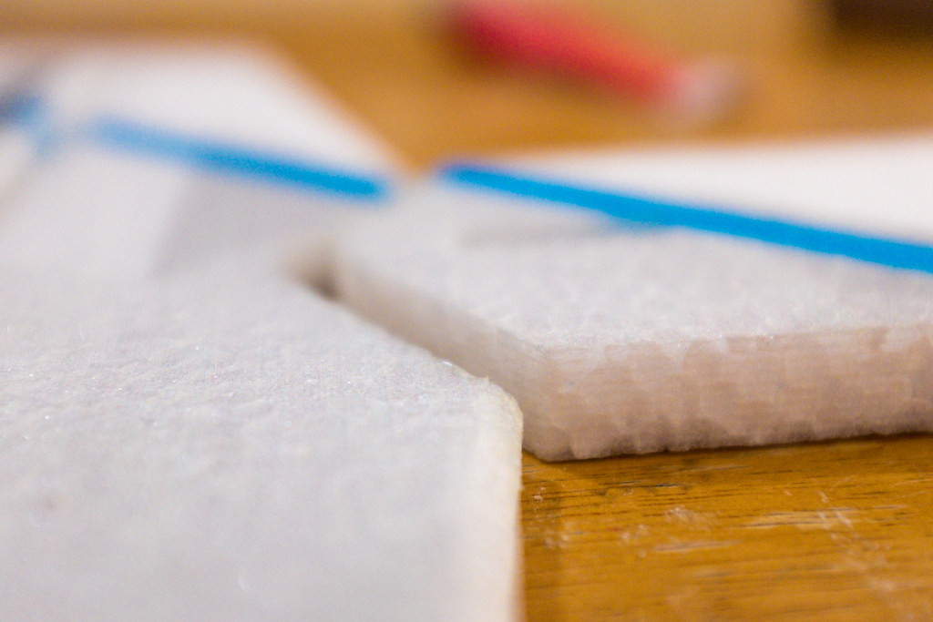
Now, with the wings firmly pressed into place against the front and back horizontal fuselage, lay your metal straightedge across the both wings with the straightedge parallel with the cut in the front and back horizontal fuselage (wow that was a mouth full). Take notice of where you make the marks on the wings. These marks are the stopping points for the cut you are about to make. Using a sharp razor, make a cut all the way through both the left and right wing, again stopping at your marks.

15103555467_8a1229698d_b.jpg

15267078786_02517f9cd3_b.jpg

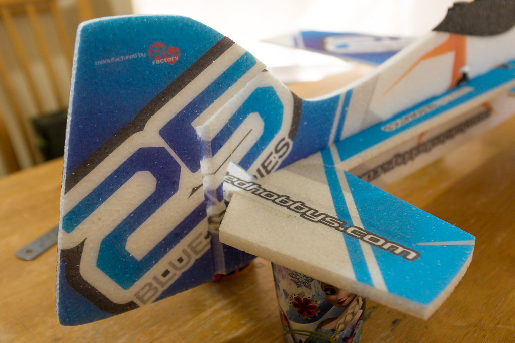
When your cuts are done, this is what it will like.

15103540518_0acd8e5c95_b.jpg

Now you want to fit the wooden spar, make sure it's pressed up against the marks on the wings. Now slip in the front and back of the horizontal fuselage, making sure everything is nice and tight. Remember we aren't gluing anything until everything is fitted, including the top and bottom Carbon Fiber Spars.

Video Summary
[video=youtube_share;gBDdtKAL3aU]http://youtu.be/gBDdtKAL3aU[/video]

15103954619_1f1dc38bf3_b.jpg

15103996210_2397d3de26_b.jpg

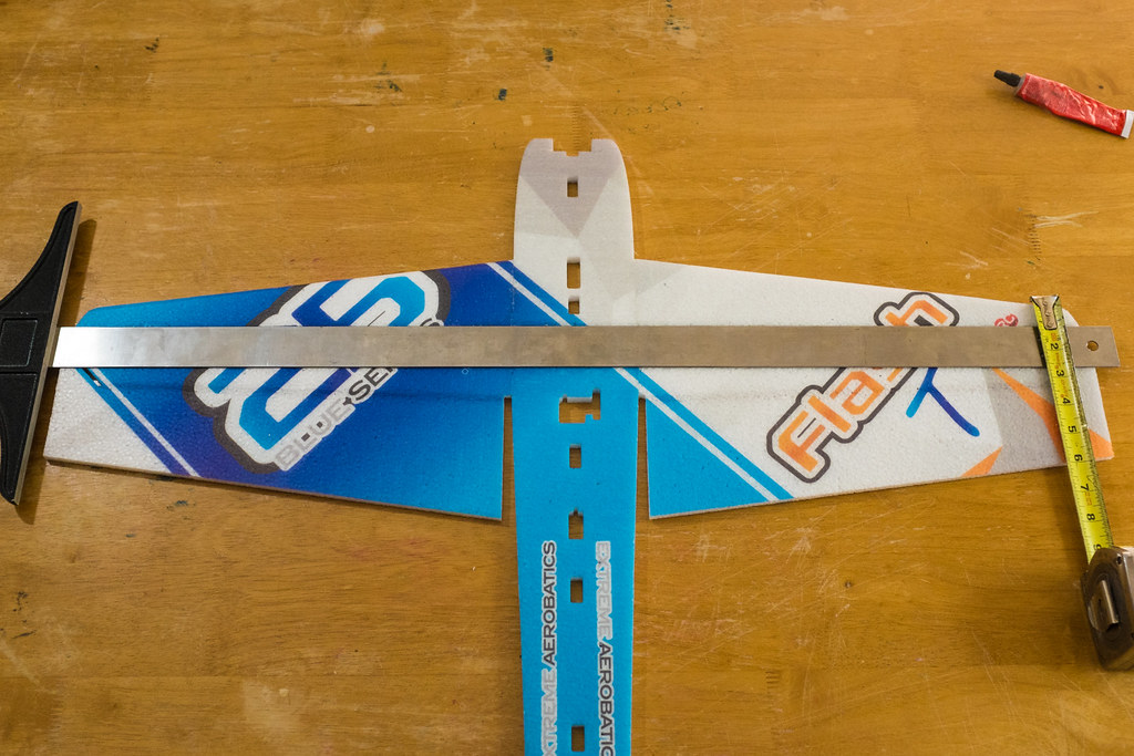
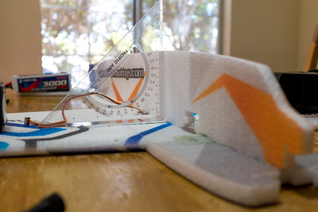
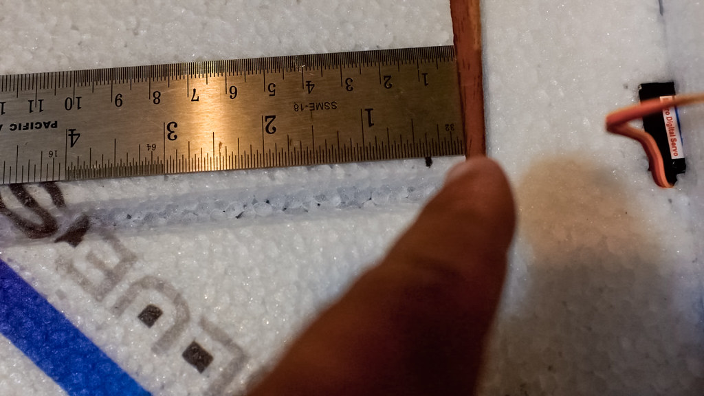
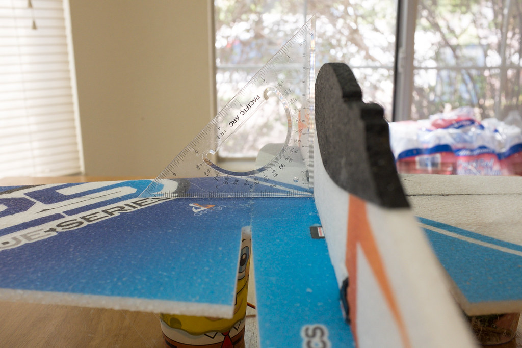
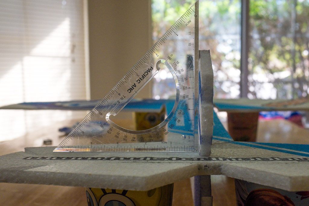
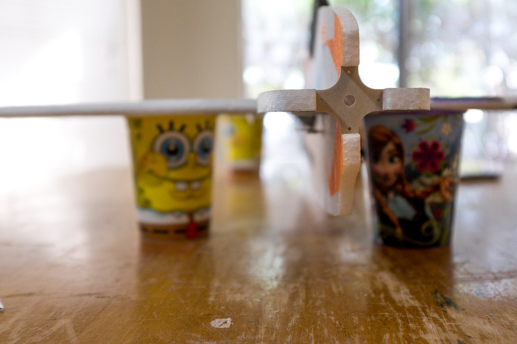
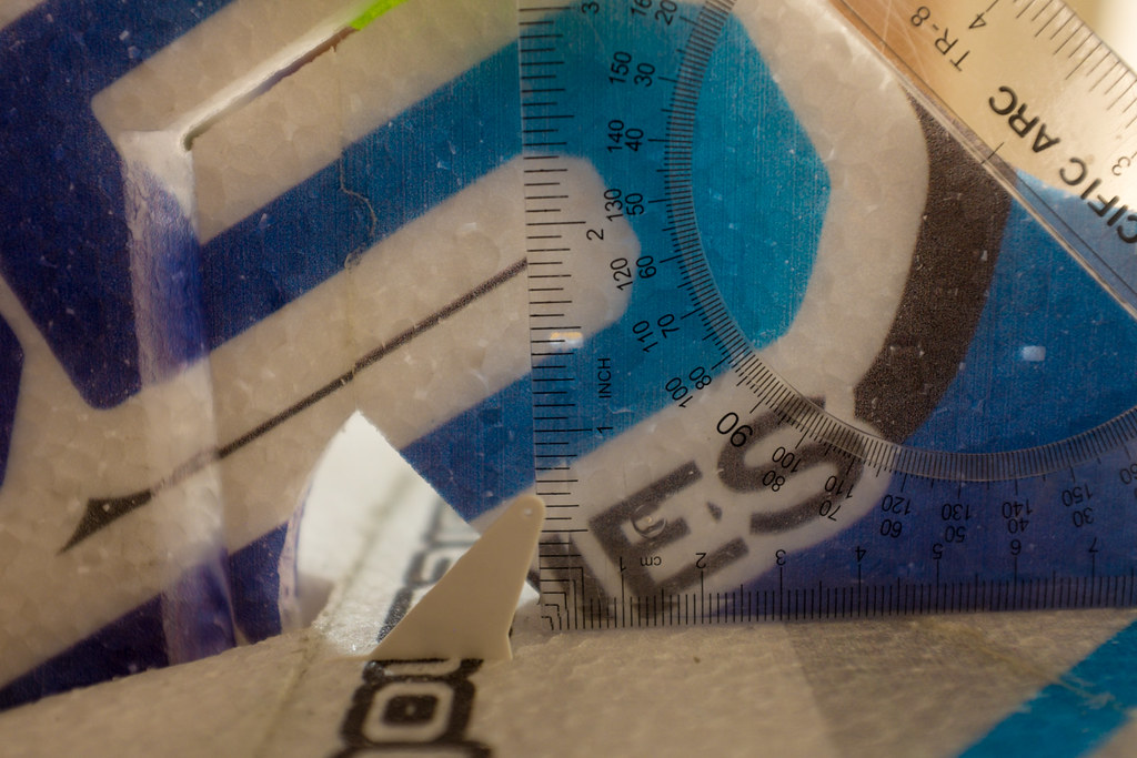
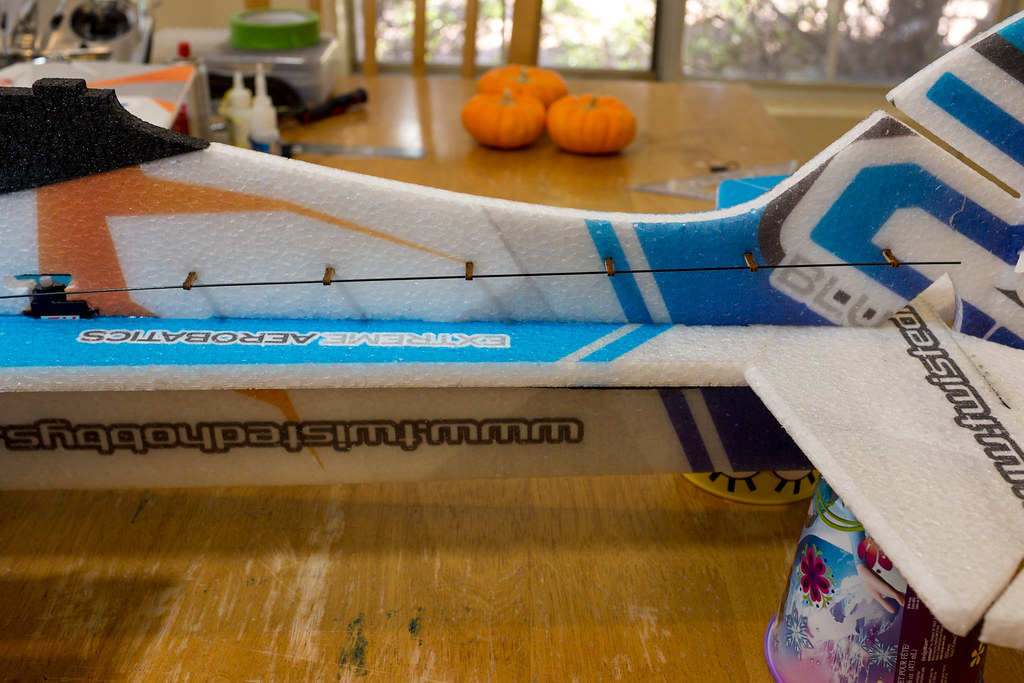
Now, with everything nice and tightly fitted, lay your long metal straight edge across the wings. make sure it is parallel and centered on the wooden spar strip.

15104151507_8252d04e59_b.jpg

15104152267_aed91f4642_b.jpg

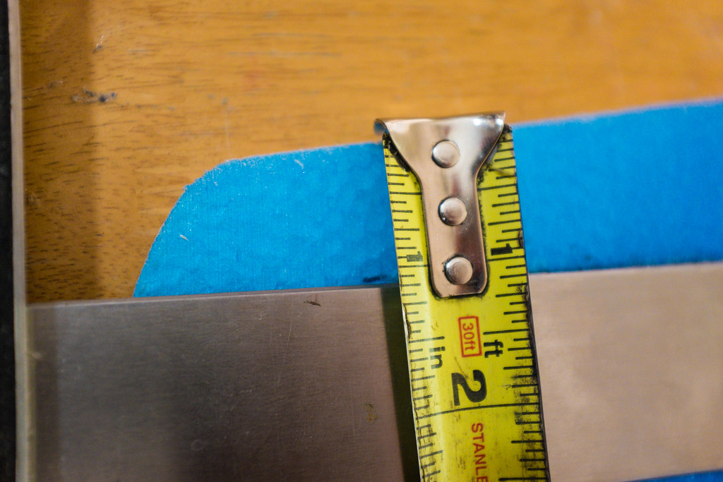
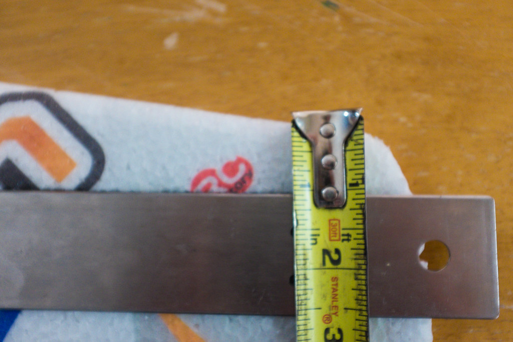
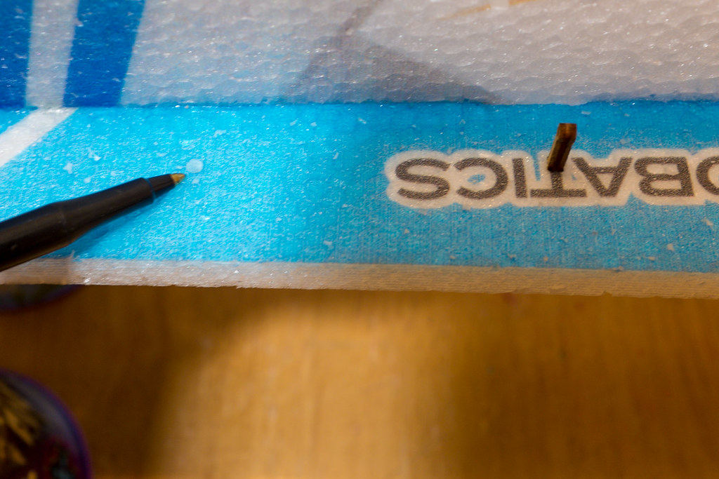
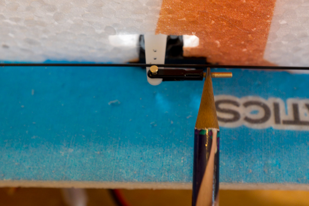
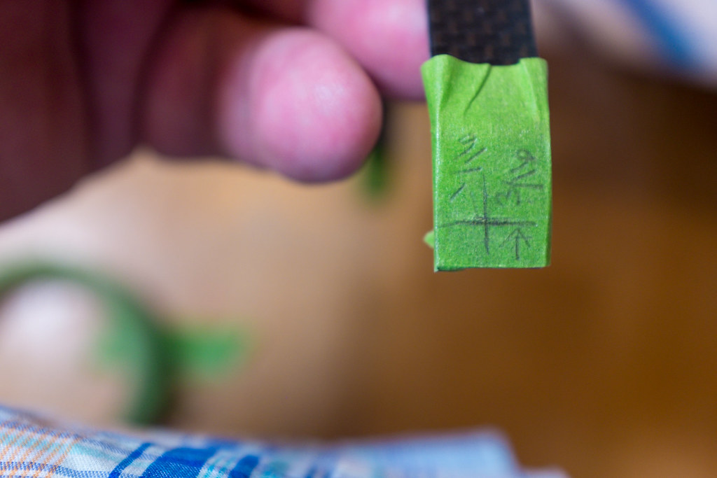
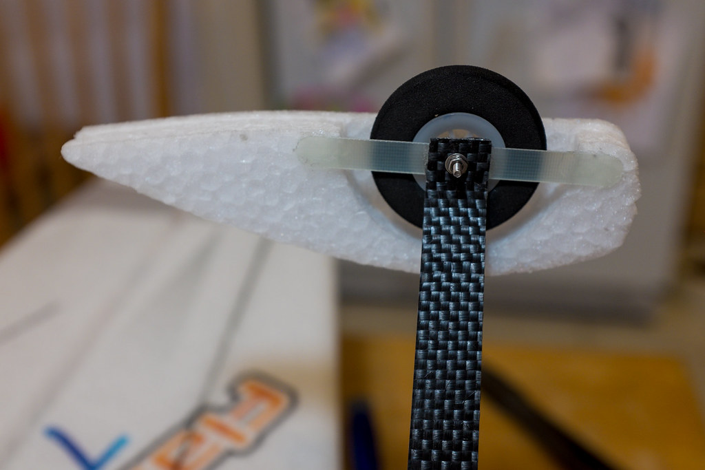
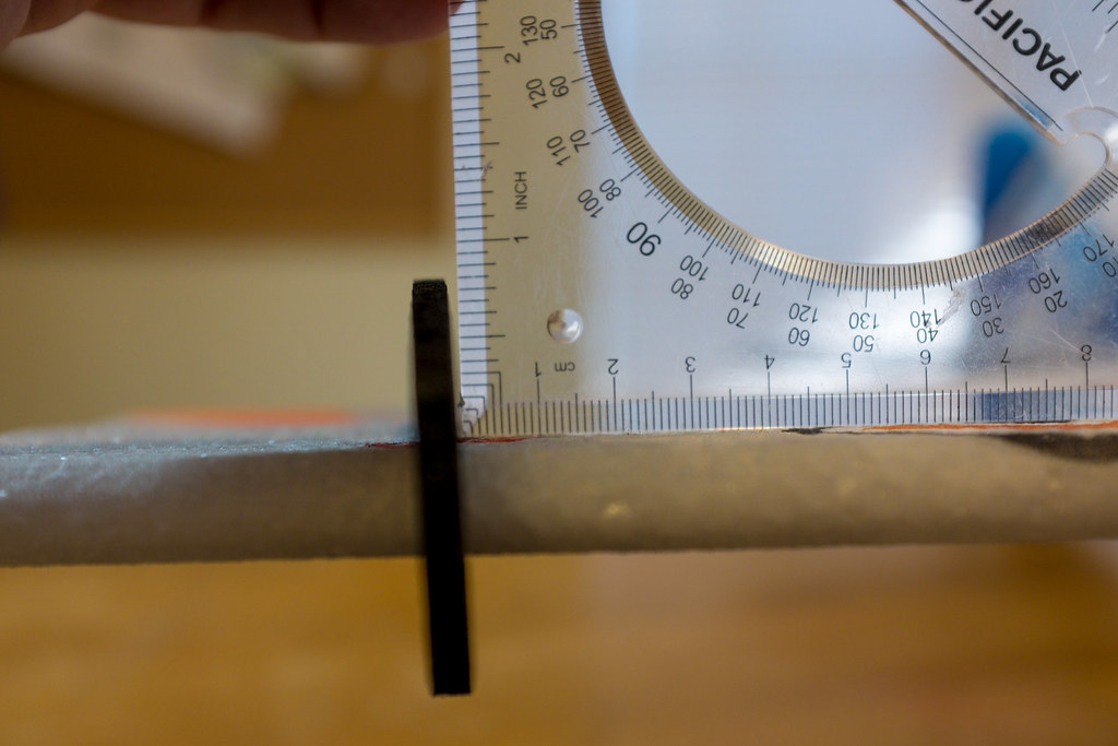
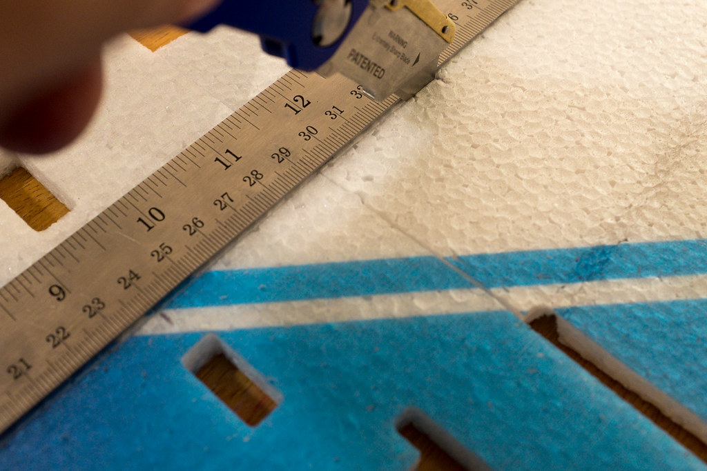
With all of the pieces firmly pressed into place, and the straightedge laying on top of the center and parallel to the wood spar strip, measure and mark 1" inch down from the leaden edge of the wing on both sides. These marks will keep you lined up correctly when you make your main spar cuts. Also lay up the carbon fiber spar, just to measure it from side to side to make sure it's in the center of the wing span from left to right. I took note on the yard stick so I would know when to stop my cut. (see the video for a visual explanation)


15290321062_bc25a91aeb_b.jpg

15104152927_3fa76cedbc_b.jpg

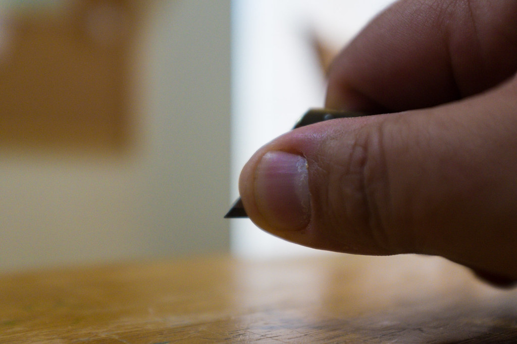
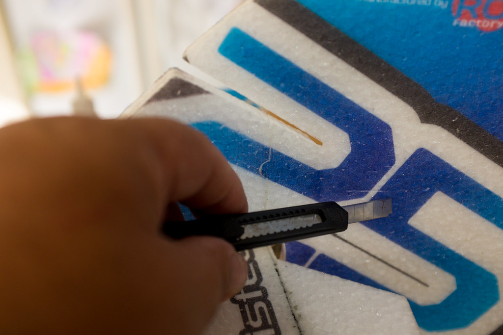
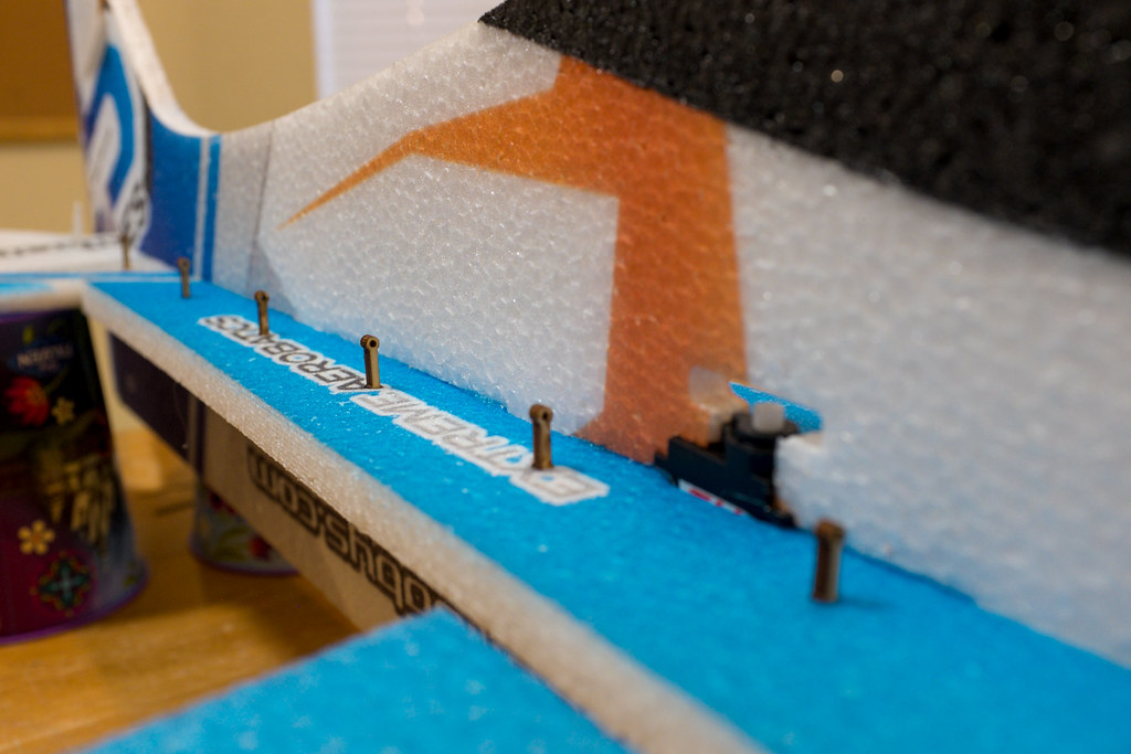
When you make your cut to embed the carbon fiber spar, you want to be careful not to go to deep. I use my thumb as a guide to rest on the straight edge. For that reason, I like to use a standard utility knife to make these types of cuts. The idea here is to just cut deep enough so the carbon fiber spar sits flush (or slightly below) with the surfaces of the wing. Be careful and make your cuts, stopping at the end where the spar stops. Then flip the plane over and repeat the process. Just be careful, take your time, and make sure everything is nice and tight before you make your cuts.

Video Tip, Embedding the Top & Bottom Spars
[video=youtube_share;stt_25zPwsU]http://youtu.be/stt_25zPwsU?list=UUCa6sk3mAf6dT4wY9TYaNNg[/video]
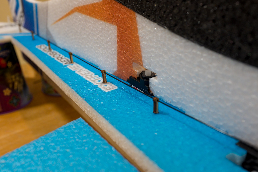
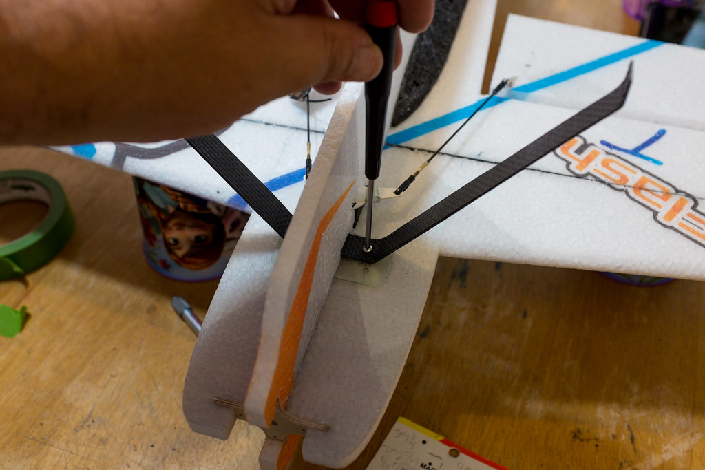
The Bottom Spar Install
[video=youtube_share;bbvtaNEJRwg]http://youtu.be/bbvtaNEJRwg[/video]

15335906802_fd40b5852f_b.jpg

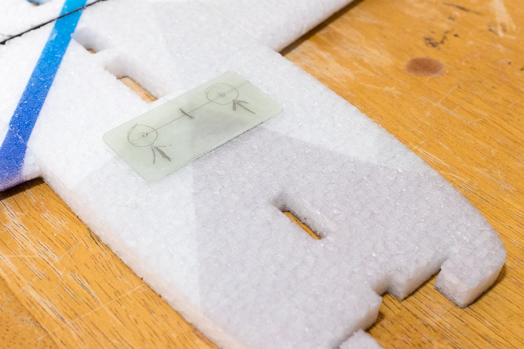
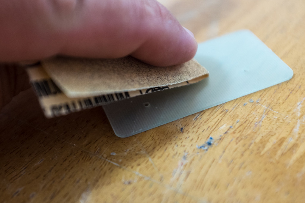
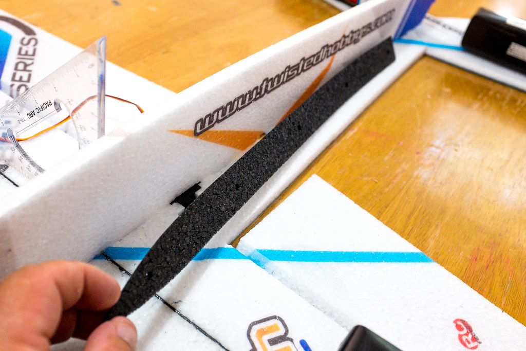
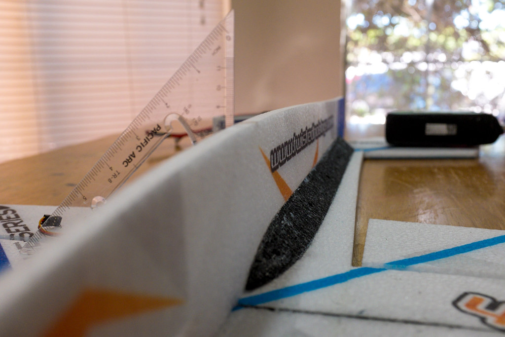
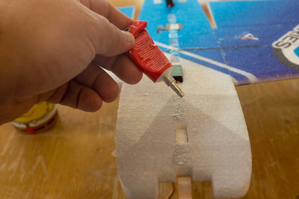
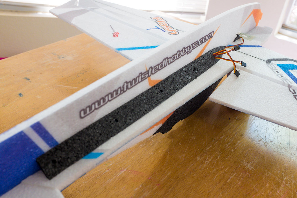
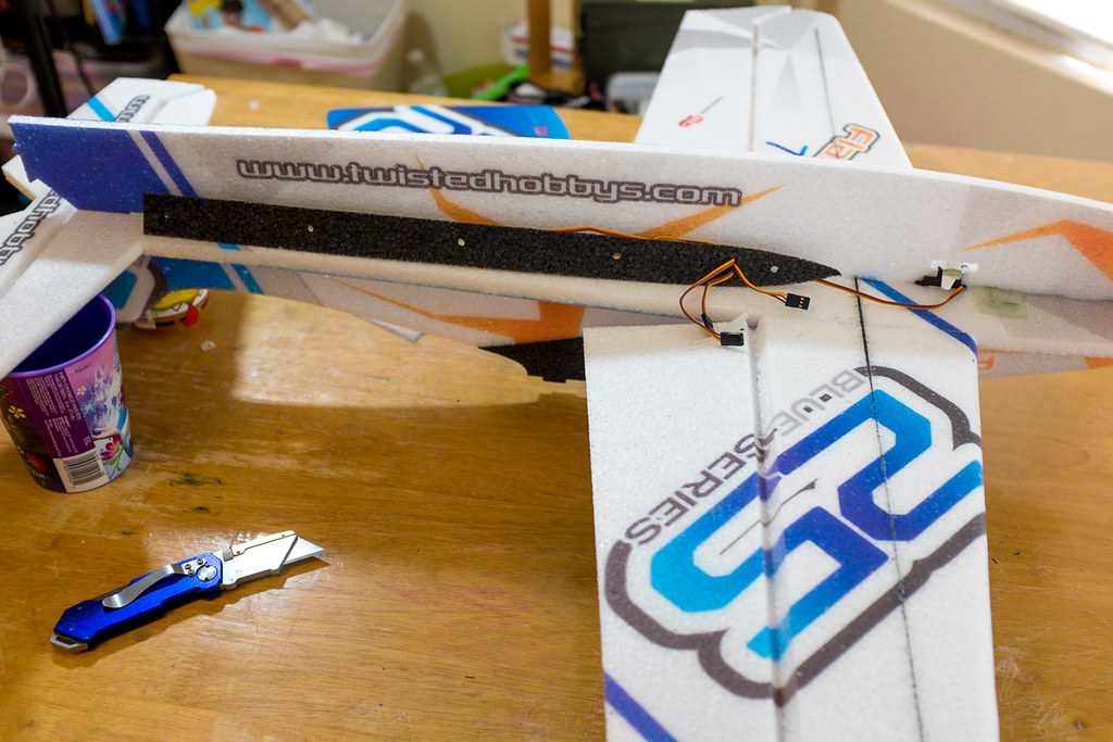
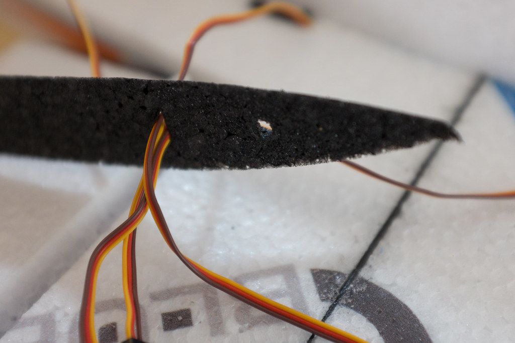
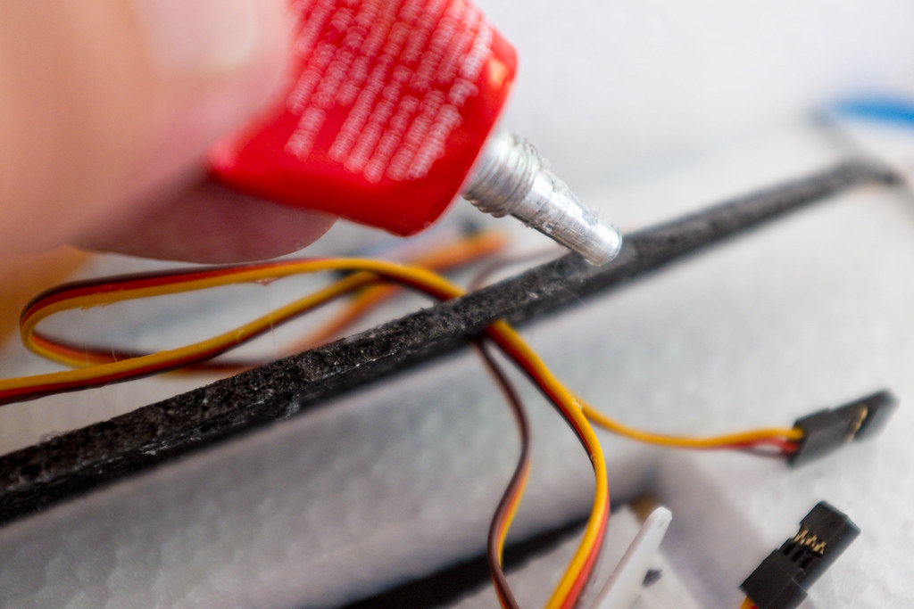
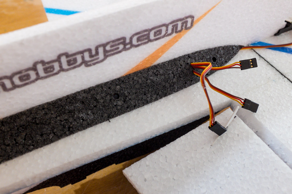
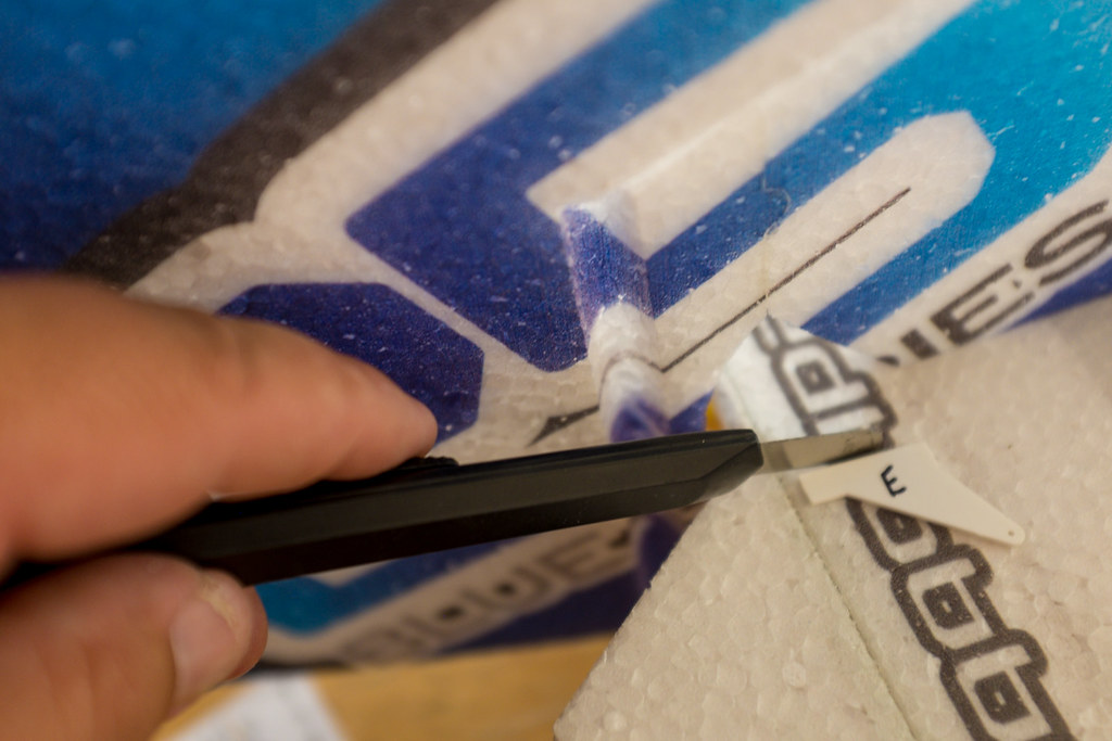
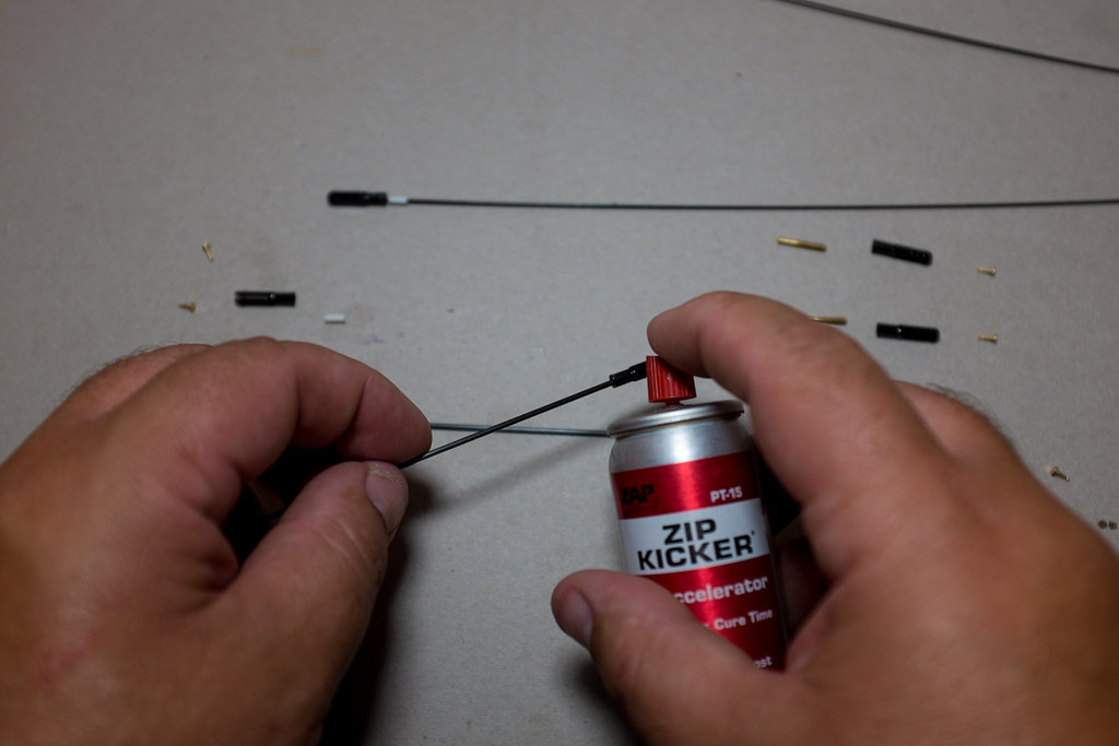
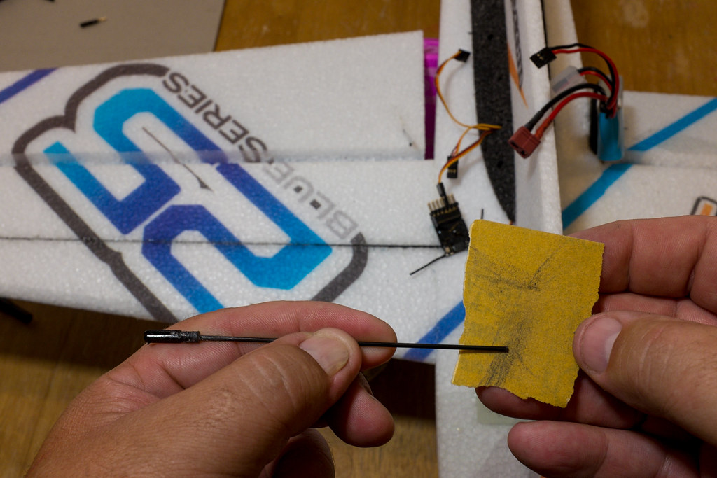
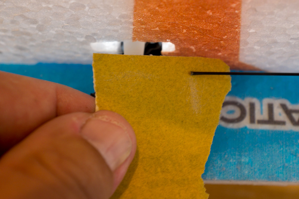
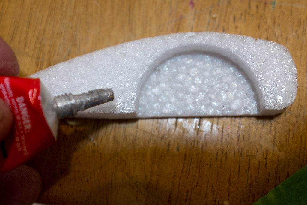
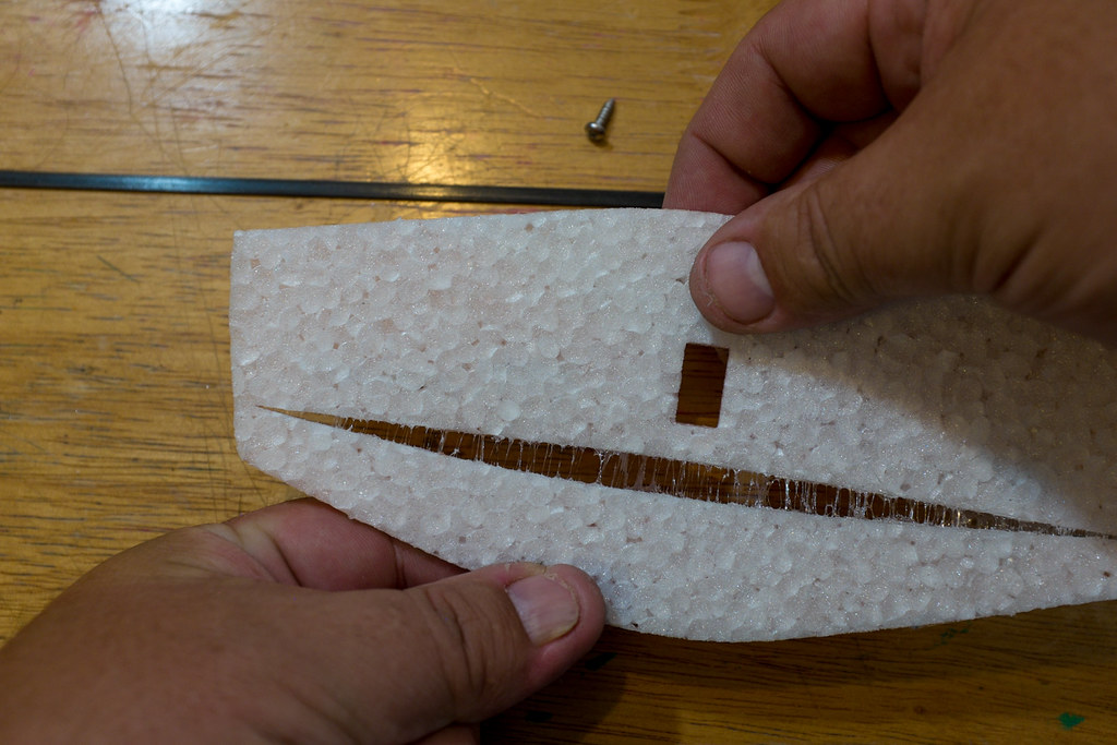
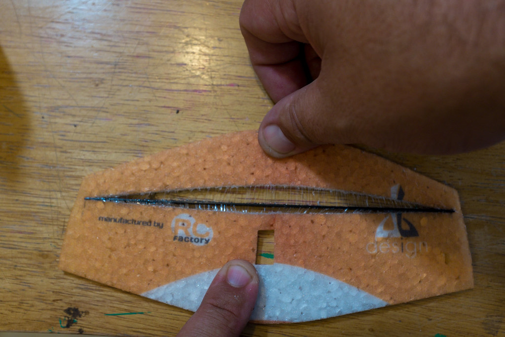
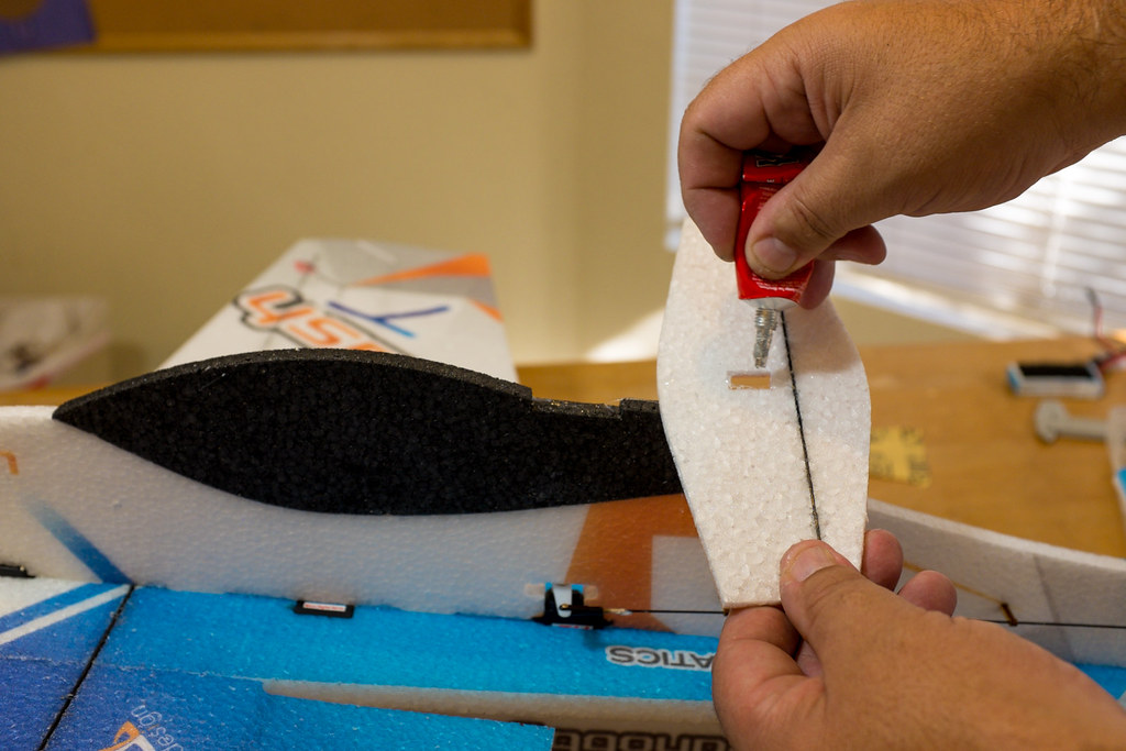
The Next step is to install the carbon fiber reinforcement strip into the base of the horizontal stabilizer (the elevator). Just use a straight edge, and a sharp razor to open the pre-existing slot placed by the factory. When you glue in the carbob strip, be sure to rough up the surfaces with 120-150 grit sand paper. Also when you glue the seams andthe strip, we want to use the wet method of gluing with welders. Well not exactly wet, but semi wet. Glue up all of the surfaces, then install the CF strip. Then remove it, and let the glue tack up for 2-3 mins. If you let the glue dry to the touch, it's very difficult to install the carbon strip. You need to be able to shift the strip into place, much like you did with the main spars.
Tips to Install the Carbon Fiber Reinforcement Strip
http://youtu.be/8kQND52WvPM?list=UUCa6sk3mAf6dT4wY9TYaNNg


15149525579_2f41cb1801_b.jpg

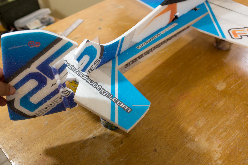
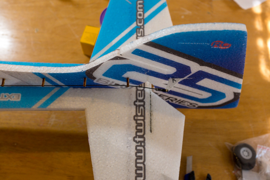
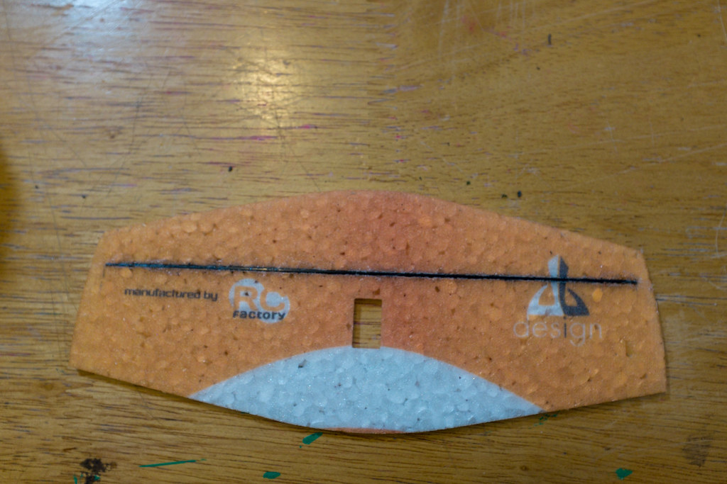
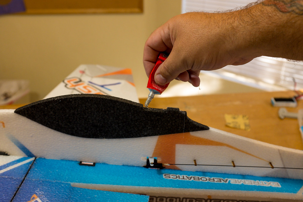
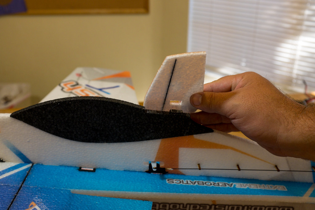
Attaching The Horizontal Stabilizer/Elevator To The Fuse

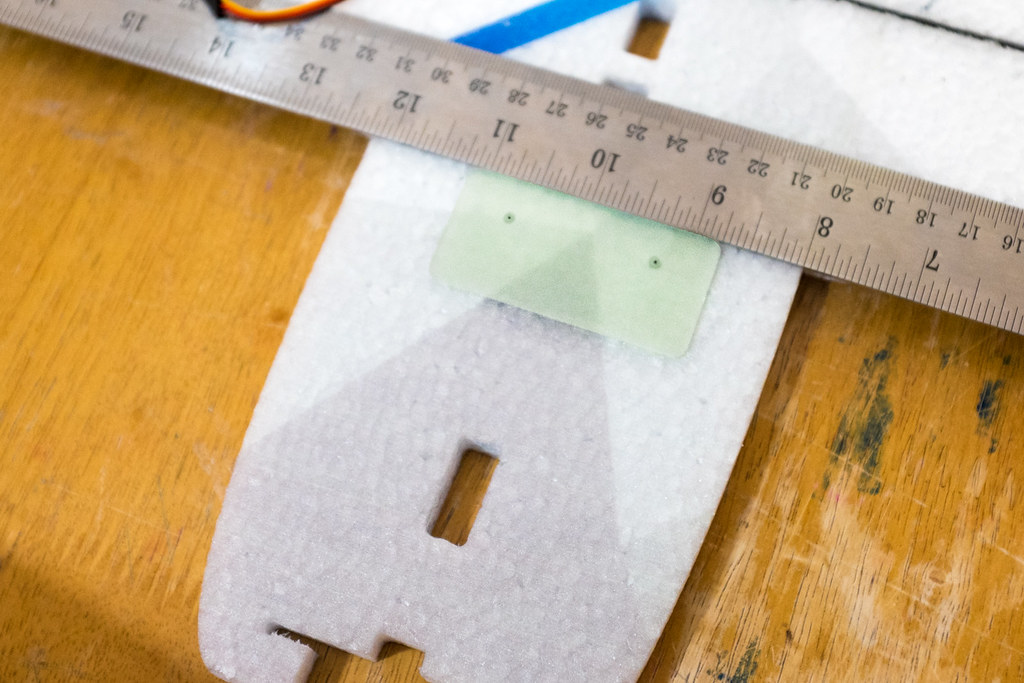
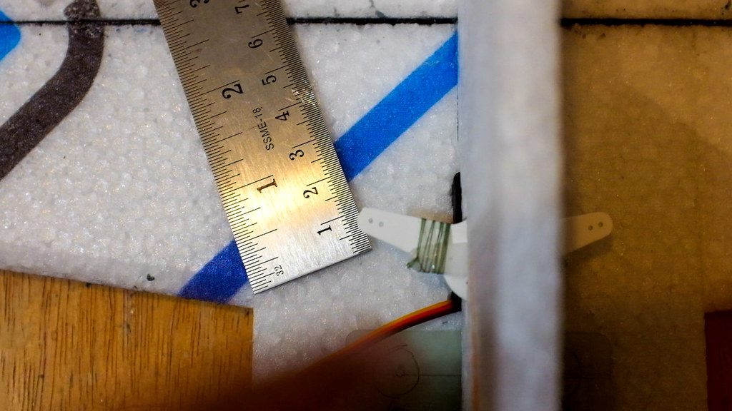
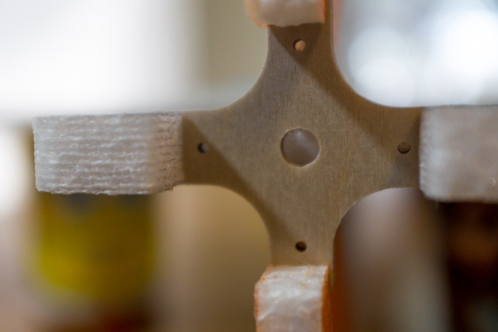
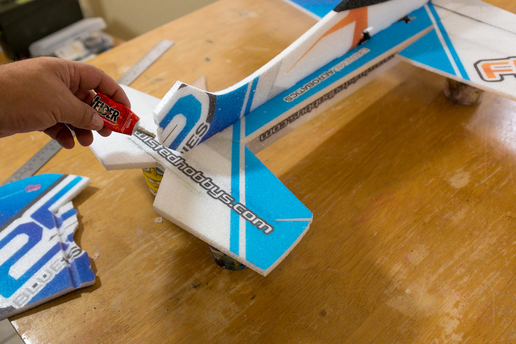
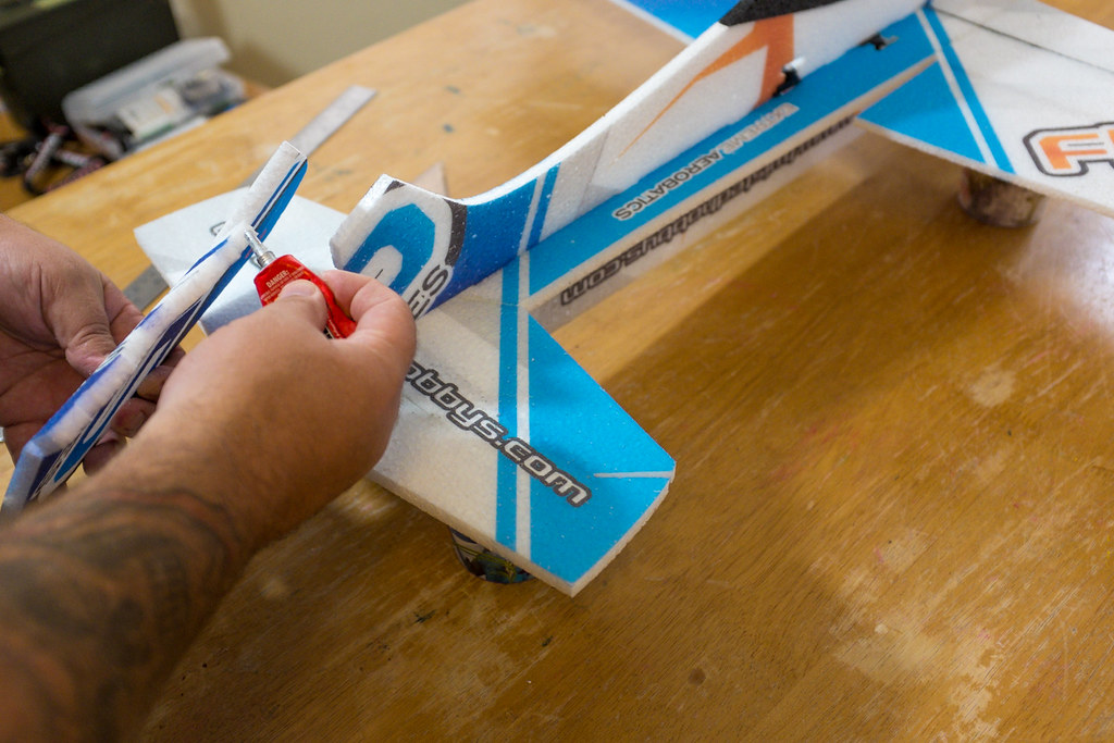
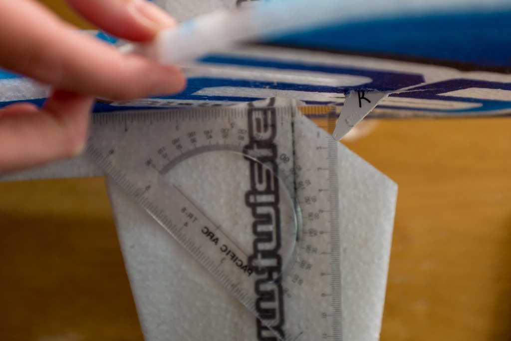
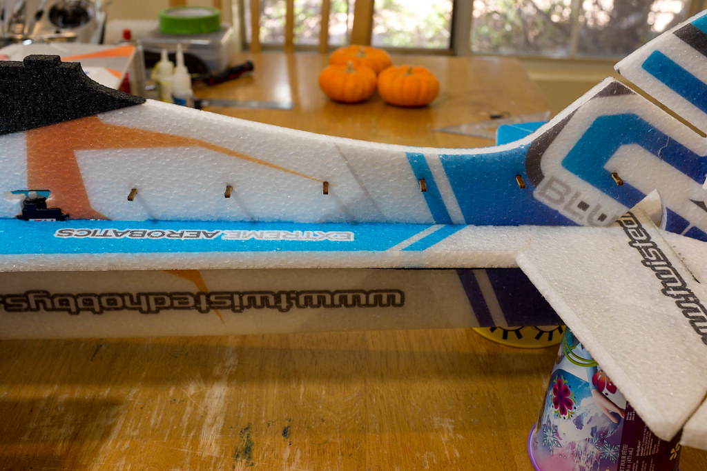
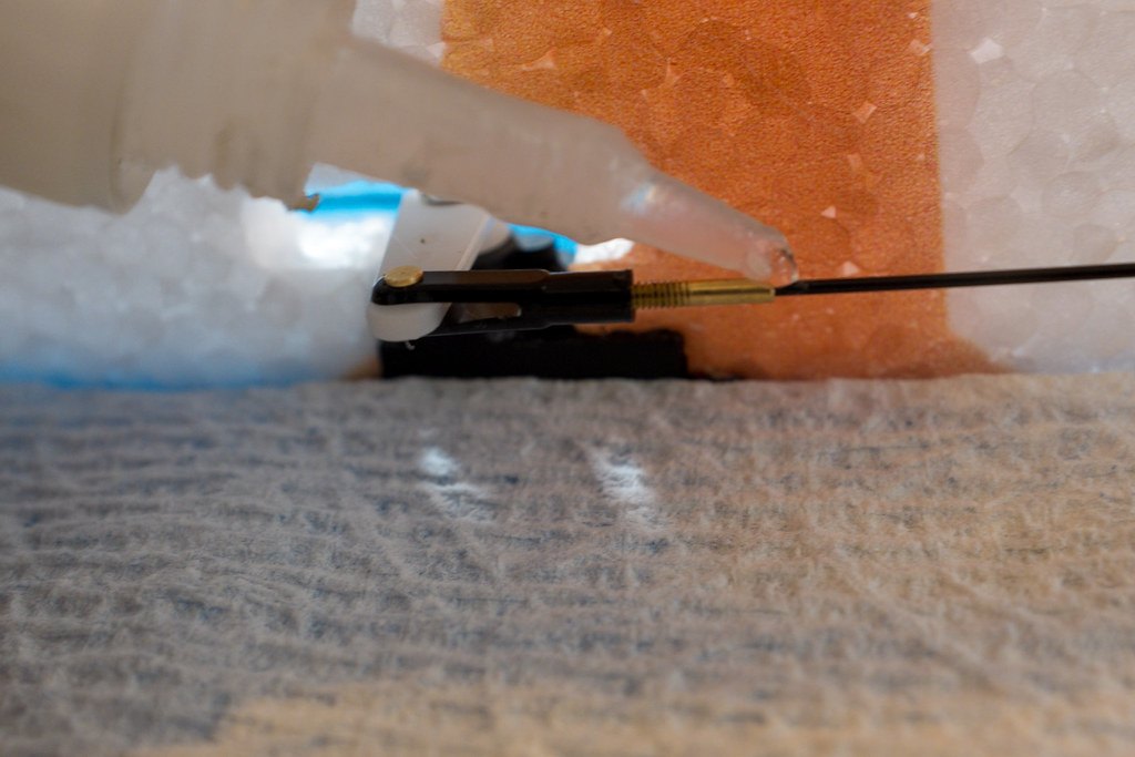
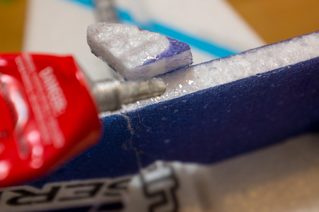
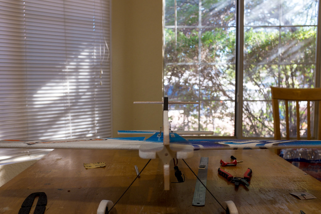
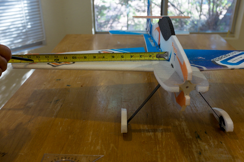
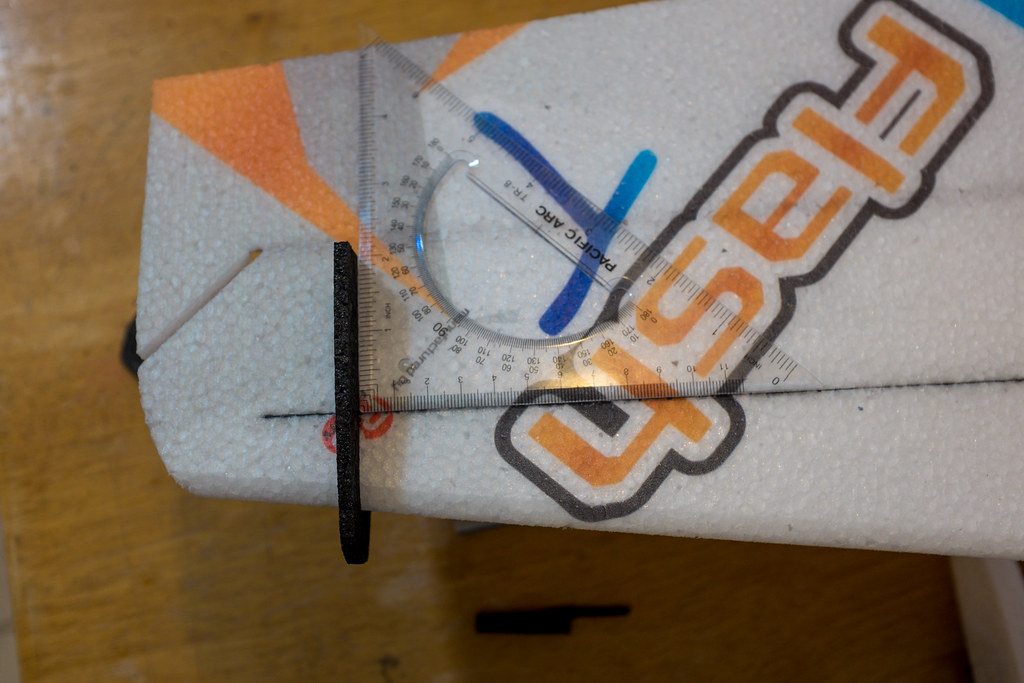
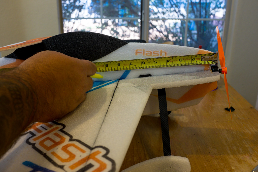
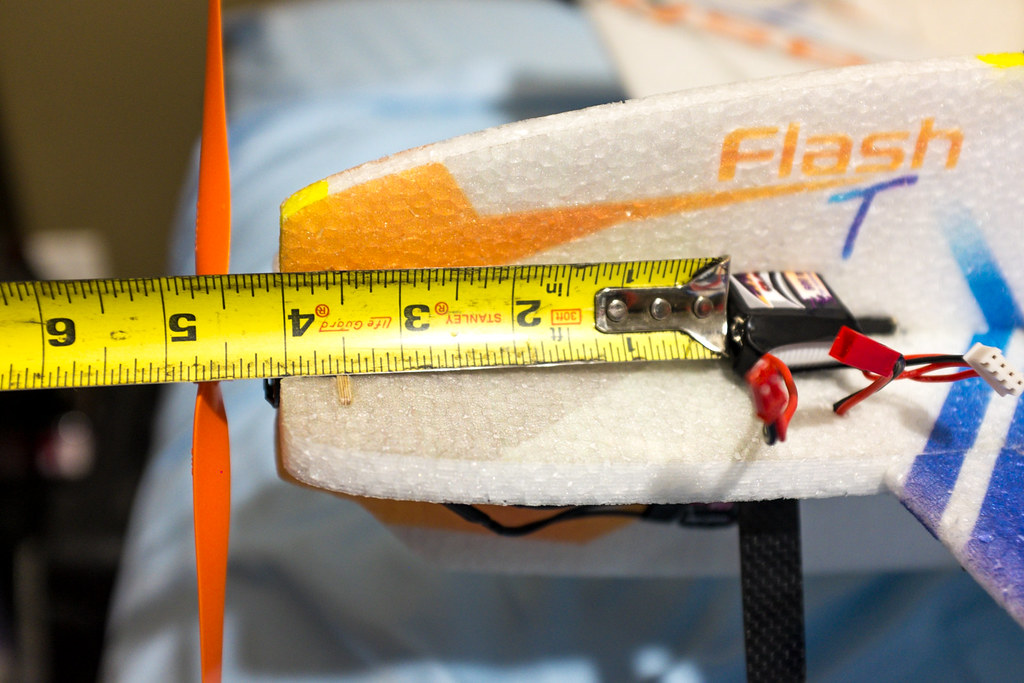
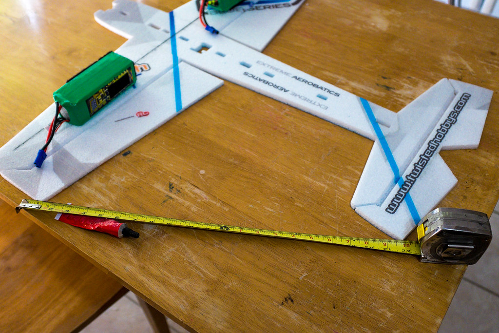
Now its time to attach the horizontal stabilizer to the fuselage. You need to use a tape measure of some sort to insure the tail is square to the wings, and you need to make sure the horizontal stab is flush to the top of the horizontal fuselage. When gluing the stab to the fuse, you need to use the dry method of welders glue.

I find flipping the wings/fuselage so the top side is facing down to be the easiest way to install the horizontal stabilizer. I say this because this will insure the fuselage is flush with the horizontal stabilizer. If you glue the stabilizer on flush to the bottom of the horizontal fuselage, the lower vertical fuselage will have a gap when you try to install it because the horizontal fuselage and the horizontal stab are two different thicknesses.
15149711898_1b4eab9d97_b.jpg


Video Tips To Attach The Horizontal Stabilizer To the Horizontal Fuselage
[video=youtube_share;1R_-B1ptbTE]http://youtu.be/1R_-B1ptbTE[/video]
 
Last edited by a moderator:

AKfreak

150cc
15313740956_8d8fc732b7_b.jpg

Landing Gear Reinforcement Plate Install Plus Tip To Set Up The Landing Gear
Now it's time to install the little fiberglass plate that serves as a platform to mount the carbon fiber landing gear. This plate needs to be installed with the holes facing towards the tail of the plane. Also the holes are supposed to line up with some preexisting holes that are in the fuselage from the factory. If the holes don't line (side to side) up exactly on your model, it isn't a problem, Just center them side to side.

15150240047_2904b6d2d8_b.jpg

Start off by sanding the fiberglass plate, and placing a mark the center of the plate. Also mark the center of the fuselage, as this will serve as register marks when install the plate.

15334401121_8c21b4eaef_b.jpg

Also you can use you use a straight edge along the leading edge of the wings to help hold the plate square to the center line of the horizontal fuselage. Just be sure to use the holes in the plate, and the holes in the fuselage as a reference for placement front to back of the fuselage.

I want to jump ahead a little here for a minute, because it will save you time and effort later on. You see, I have built several other TH/RCF models with carbon fiber landing gear in the past. The instructions tell you to measure in mm and make various marks on the landing gear before you drill it, its kind of a pain to convert metric, and layout the holes. There is an easier way.

Just use the fiber glass plate as a template before it's mounted to the plane to lay out the holes on the landing gear. All you have to do is put a piece of tape on the top face of the landing gear. Then mark a center line (both width and length) on the landing gear, and line up the center line on the Fiberglass landing gear plate with the center line you marked in the landing gear. Then use a pencil to mark the holes. It sounds more complicated than it really is. Please take a few mins and watch the video below to see what i'm trying to explain.
[video=youtube_share;DAgCyJQOpoo]http://youtu.be/DAgCyJQOpoo[/video]


15151055138_730c509286_b.jpg

Servo Fitment

The servos have been cutout in the fuselage for precise placement, however since servos do come in many different shapes, the final fitment is up to you. I highly recommend the power combos sold at Twisted Hobby's, because the servos fit perfectly. Even so you still need to make notches for the tabs.

15337645945_bdfd612d74_b.jpg

Press down on the servo while it is sitting where it is supposed to be in it's final position. This will leave little indention's that you can use as a guide to cut with a small razor knife and a straight edge.
15151109357_a374674bce_b.jpg

When you cut in the tabs, cut them a little smaller than the actual thickness of the tab. If you do, the servo will slide into place and be nice and tight. Also, do not glue any of the servos in place until the end of the build. We will use strategically placed hot glue to hold the servos in place because if one fails, you will not have to destroy the model trying to replace one.
15314608076_6471fb9c51_b.jpg


Servo Fitment Video Quick Tip
[video=youtube_share;K7kx8gcMaSA]http://youtu.be/K7kx8gcMaSA[/video]

15338167325_04e167c11e_b.jpg

Vertical Fuselage Separation

Now its time to install the lower vertical fuselage half. However when the model is shipped, the vertical fuselage is all one piece, you need to separate it into two pieces (a top and a bottom). Also there is a little tail hook piece, so don't loose it, you will need it at the end.

15334985871_30365288b1_b.jpg

If you look closely at the rectangle openings at the center of the vertical fuselage, you will see these little notches at each one.

15334983981_bc60f85b20_b.jpg

Those notches are there so you can line your long straight edge to use a razor knife to cut to the vertical fuselage in to two separate pieces (top and bottom).

15338169405_0b20d1fb8e_b.jpg

15315132836_024a70bdd1_b.jpg

Also remove this little tab from the elevator opening. This will serve as a tail skid later in the build.

Vertical Fuselage Separation Video Tip
[video=youtube_share;F7_U0qWbr1Y]http://youtu.be/F7_U0qWbr1Y[/video]

15315356796_22a3032e16_b.jpg

Lower Vertical Fuselage Install

Now it's time to install the lover half of the vertical fuselage. You need a square, and we will be doing a standard dry welders glue joint. Do an initial fitment of the lover fuse half, taking a peek at the tail where the horizontal stabilizer meets the lower vertical fuse section. Make sure there is not gap there, because if you have a gap, the horizontal stabilizer is glued on wrong.

15338081742_4a3fbc2843_b.jpg

Now grab the welders glue, and be sure to glue both the lower fuse half as well as the center-line of the horizontal fuse section. Try to keep the glue off of the servo cut outs. be sure to spread the glue evenly on the lower vertical fuselage half. Make sure you get glue on the entire surface where it will be joined, then carefully fit it into place. Rock the lower fuse section back and forth from side to side to ensure the edges of the lower fuse make good contact with the horizontal fuse. Next pull the lower fuse back off, and let it sit for 5 to 10 minutes or until both glue surfaces are dry to the touch.

15151806288_5a3515760a_b.jpg

Now it is very important to weigh the plane down so it will remain flat during the lower fuselage section final fitment. Now, after the glue is dry to the touch insert the lower fuse half back into place. Make sure to use your square to keep the lower fuse at 90° to the horizontal fuse/wings. Be sure to rock the lower fuse back and forth so the edges of the lower fuse bond well.

Lower Vertical Fuselage Install Video Tip
[video=youtube_share;4M07r3JNXjQ]http://youtu.be/4M07r3JNXjQ?list=UUCa6sk3mAf6dT4wY9TYaNNg[/video]


15335210521_1b373733f9_b.jpg

Lower Vertical Fuselage Brace Install
Now grab the black 45° tapered brace and wet it up with welders glue. I pre-fit this brace and mark it front to back so when its wet with glue, I know exactly where it goes. This time, you will only glue the brace side with welders, and be a little liberal with the glue. Now using your placement marks, press the 45° brace into place while being as gentle as possible. You are tying to transfer glue from the angle brace to both the horizontal and vertical fuselage while maintaining that 90° between the lower vertical and horizontal fuse sections. Pull the brace off and let it dry for 5 to 10 minutes.

15335210231_a437f1be0f_b.jpg

With the glue dried, and the square on the opposite side of the lower vertical fuselage. Start at the back and work your way forward. Start fitting the angle brace into place, but be sure to only press against the lower vertical fuselage where you are supporting the lower vertical fuselage directly on the other side with the square. Failure to support the fuselage with the square, can result in a crooked lower fuselage and cause the plane to have poor in flight performance (see my video tip below).

Lower Vertical Fuselage Bracing Install Video Tips
[video=youtube_share;s3HxwTRQN7M]http://youtu.be/s3HxwTRQN7M[/video]


15315355616_fc16be7d07_b.jpg

15152390260_ef250a0757_b.jpg

Aileron Servo Install
Now its time to install the Aileron servo. Not only will we place the servo, we will prepare the servo extension so we can achieve maximum throw in the Ailerons. The servo hole for the Aileron is all set up and ready to fit a TH CS-90D (9 gram servo) without any sort of cutting or tab reliefs. All you need to do is make sure the offset in the top of the servo is facing forward, and you feed the wire on the same side as the other servo wires.

Aileron Servo Fitment Video Tip
[video=youtube_share;rHfdr3phQXg]http://youtu.be/rHfdr3phQXg[/video]

15152518448_bef78f94b3_b.jpg

All of the control horns and aileron servo extension are tabbed together. You will need to cut out the aileron extension so you can thread it on to the control rod.
Aileron Servo Extension
EDIT Please note the aileron Servo extension is shown and installed backwards in this thread. Please make sure the tips of the extension face forward and act as a differential to insure the ailerons deflect equally in both directions. It's calked a differential servo arm, and I faced it backwards in this build. It's an easy fix, just unscrew the arm and turn it 180 degrees. I hope this edit helps you avoid this mistake.

15338791422_54e8da6a1e_b.jpg

To set up the servo arm extension, you need to grab the biggest two sized servo arm from the package the servo came in (don't lose the mounting screw). To mount the extension to the servo arm, I like to use Spyder Wire (braided fishing line), but dental floss, fine twine, even some sewing threads will work to thread the two parts together.

15152573087_8ebd79121f_b.jpg

15335925111_e86f1075f9_b.jpg

First center up the servo arm on to the extension as shown above. Then tack it with a little CA to hold it into place when we thread it.

15338790172_7c35e6eb70_b.jpg

15152388300_8f91a64c32_b.jpg

Now using the hole on the end of the servo arm, the one that's not covered by the extension, thread your string through that hole and wrap it tight 4-10 times (as shown), ending back in the hole you started with. Be sure to tie the thread off nice and tight, then cover the thread and servo arm end with CA. Use and a shot of Kicker if you have it, this will speed things up a bit. Repeat the process to the other side, and you are ready to move to the next step.


15339104815_b37bb77f67_b.jpg

Aileron Control Horn Install

Now its time to install the aileron control horns. Look at the picture above where I have labeled all of the control horns. They are the ones labeled, "A", and they are the only two that are exactly alike. When installing the control horns, you want to make sure the attachment hole is located in the center of the hinge line. This will insure that you achieve maximum control surface deflection, as well as equal force and travel on both ailerons.

15160824427_f82e9f4ec9_b.jpg

15347385755_ea4876d6ee_b.jpg

What you need to do is measure and mark 3/8" (three eights of an inch) in from the aileron root at the hinge line. Then use your small straightedge to make a line between your aileron servo extension arm (set at 90° to the fuselage) and the 3/8" mark at the aileron root. This will show you at what angle you need to make a cut to recess the aileron control horn. However it does not show you how far back the cut need to be to ensure the control horn attachment point is centered at the hinge line.

15160588519_9cf66c0c5e_b.jpg

To center the control horn into the hing line, I use a second straightedge that is placed in the center of the hinge line. Where the two straight edges intersect, is where the hole in the control arm needs to be placed. Lay the control horn on its side with it resting on the intersection point of two straightedges, but have it also lined up with the straightedge that runs from the servo extension to the mark on the aileron root. Lastly, repeat that process on the other wing.

Aileron Control Horn Install Video Tip
[video=youtube_share;fZM4G8OUR-Q]http://youtu.be/fZM4G8OUR-Q[/video]
 
Last edited by a moderator:

AKfreak

150cc
15357484385_d70c87a980_b.jpg

Canopy Install
Now its' time to prepare the top section of the vertical fuselage for install. In order to do this, we need to install the canopy section. The Canopy is black, and has some notches cut out that are used to mount a cantilever wing. Mount the notches towards the rear, and use the welders dry method to glue on the canopy. (A Valuable Tip. Use some drinking cups to help support the wings and elevator when you install the top vertical fuselage section)
15170906888_0ff9e65ac7_b.jpg

15357482775_9a1d1302be_b.jpg

Put welders glue on both the canopy and the top section of the vertical fuselage. Press fit both surfaces making sure that both wet glue joints press tightly together. Wipe off any excess glue that might squirt out of the sides, then pull the parts apart. Let them set up until the glue becomes dry to the touch (5-10 mins).
15170719419_b85f8cc04d_b.jpg

After the glue is dry to the touch, carefully slide the two pieces together on a flat table. Rock the joint side to side to insure the edges of the foam bonds together well. The parts should hold together pretty good at this point, but remember it will take 24 hours for the joint to fully set up.
Canopy Install Video Tip
[video=youtube_share;TCw1P5zJ3v0]http://youtu.be/TCw1P5zJ3v0[/video]

15170781290_8ac8c7b8de_b.jpg

Vertical Fuselage Top Section Install
Now its time to install the top section of the vertical fuselage. These can be a little tricky because you are going to be dealing with a servo, and you want to make 100% sure the top section is perfectly square to the horizontal fuselage. Take your time, test fit the fuselage section, and also the servo. When toy fit the servo, make sure to run the wire so it ends up in the same side as the other servo wires..
15170684359_a79689f88d_b.jpg

15170743350_8552648c18_b.jpg

The last servo fits into the cut away in the top vertical fuselage. The only thing that holds it in place until you press it into the horizontal fuselage the servo tab cut out. Remember don't be tempted to try and glue the servo it into plane just yest. We will do that at the very end. Just be gentle and press the servo in the the horizontal fuselage a little at a time while you test fit the top vertical fuselage section. Make sure everything fits perfectly, then slip it all apart to glue it.
15170681409_75095f86e8_b.jpg

15357126482_a34f642929_b.jpg

After you test fit everything, now it's time to glue it all up. Use the welders dry method here. Make sure not to get glue on your servo joint, and do route the servo wire to the correct side, the side with the other servo wires. Wet both surfaces (vert fuse, and horz fuse center), and all of the key ways. Now press your parts firmly together, then pull them apart and let them dry for 5-10 mins. When dry to the touch, they will be ready for final assembly.
15357125472_07e3ff4aff_b.jpg

15357126062_6189a14c78_b.jpg

Use Cups or somthing to hold the plane flat as you press fit the now glued top vertical fuse section back into place. Gently slide top vertical fuselage section with the last servo installed into place. This will take some extra effort, so take your time. Once the vertical fuselage section is sitting tight and locked into place, use your square to make sure it's sitting 90° to the horizontal fuselage. Be sure to check square in the front, middle, and back for squareness.

Top Vertical Fuselage Install Video Tip Sorry the video is 9 mis long
[video=youtube_share;gSx8hglPsyo]http://youtu.be/gSx8hglPsyo[/video]

Second 45° Degree Fuselage Brace Install
15170862308_0193dc9b32_b.jpg

The second 45° degree fuselage brace is a bit more tricky than the first because you have to deal with servo wires. Again all you need to do is take your time, and follow these simple directions.
15357439885_5b1fb2d46b_b.jpg

15170864288_b3b8920924_b.jpg

First set the brace up on the plane in such a way that you can see to line it front to back with the previous brace installed. Then visualize all of your servo wires coming through the brace and maker a small slice in order to feed all the wires through (don't worry about the ESC servo lead.)
15170911167_e562cd7850_b.jpg

With the wires coming through, just lay the brace over on its side, and apply a nice bead of welders glue on both beveled sides. Remember you need glue so it will transfer onto the fuselage when you fit it into it final resting place. After you have glue on both the beveled edges (all the way to the tip) press it against the fuselage. Press it to transfer some glue while trying not to get any glue on the wires by tucking them down against the fuselage. Then peel it apart and let it sit for 5-10 mins, or until dry to the touch.
15354249551_5cbb8930dd_b.jpg

Now its just a matter of fitting it gently back into place without pinning any of the servo leads between the brace and the fuselage. I press the entire brace into place very lightly, then I rub the edges to seal it down without actually moving the lower vertical fuselage. The brace we installed on the other side is keeping everything square, this brace will just add more support. Just take your time, and it will fit very nicely.

Second 45° Degree Fuselage Brace Install
[video=youtube_share;1OWBlm2Msho]http://youtu.be/1OWBlm2Msho[/video]

Motor Mount Install
15170907607_10f8ac6772_b.jpg

The Motor mount is simple to install. Just put glue in the four slots at the nose of the plane, and press the tabs directly backwards to spread the glue on both sides of the foam at the motor mount slot.
15354246631_90f41be702_b.jpg

Then bring the wooden mount into place by rotating it 45° degrees counter clockwise and line it up with the four slots.
15170734120_39d455c960_b.jpg

Rotate the tabs clockwise fitting each of the four tabs in to the now wet glued slots. Press the tabs from the front to apply pressure to the glue so it transfers from the foam to the wood. After 24 hours that brace will be rock solid. However, if you feel you need more glue, just add it in from the back side of the motor mount at the foam, and call it done.

Motor Mount Install Video Tips
[video=youtube_share;l82knYMyxSQ]http://youtu.be/l82knYMyxSQ[/video]

The Rudder Install
15334415536_2ed450754f_b.jpg

To install the rudder, its really easy. We will do a dry welders joint, and press fit the rudder in to place. Since we did a good job at installing the top and bottom vertical fuselage sections. Installing the rudder is a piece of cake.
15357434625_8b91032d81_b.jpg

15170857938_9aafd049be_b.jpg

Apply welders glue to both the plane and rudder side contact surfaces. With both sides wet with glue, fit them together, being sure to wipe off any excess. Then pull the glued rudder section off and let it dry to the touch (5-10 mins).
15334415536_2ed450754f_b.jpg

15170905537_3ac607028a_b.jpg

After the glue dries, fit the pieces back together being careful that they are properly aligned. There are alignment notches that help you with vertical alignment, but you need to make sure the rudder is attached properly from side to side. I fit the pieces loosely at first, making sure everything is perfect, then I press it all down. I will say that working from the cups makes this job a lot easier than without.

Rudder Install Video Tip
[video=youtube_share;JgGpsA8Bg7c]http://youtu.be/JgGpsA8Bg7c[/video]

Elevator & Rudder Control Horn Install
Now we need to install the elevator and rudder control horns. We will use welders glue, and we will insure that the eyelet that attached to the control rod clevis is centered into the hinge line.

15385331746_d098b01a0e_b.jpg

15408367975_68529f531f_b.jpg

We start off by grabbing a razor knife and opening the slots that are placed there by the factory on the elevator and the rudder.

15221613249_290ee93ae5_b.jpg

Gluing up the control horns is really easy. Use Welders and put it on both sides of the control horn, also squeeze some in the slot on each control surface. Test fit the control horns with the glue on them, making sure to wiggle them back and forth spreading the glue all over the base of the control horns. Then pull the horns and let the glue tack up a little, but not dry to the touch. Fit the horns back into the slots and line them up as shown below and in the video.

15405184351_ebe77b5bf4_b.jpg

15221766368_5f3aec9034_b.jpg

Make sure to line the control horns line up so the eyelet (hole) that connects to the control arm clevis is centered in the hinge line. then we move on to the control rods.

[video=youtube_share;Kwcei0Cd_6I]http://youtu.be/Kwcei0Cd_6I[/video]

Setting Up The Aileron Control Rods
EDIT Note the Aileron servo horn in these pictures is backwards. The tips should face forward to insure equal control surface deflection. It's called a differential servo arm, and again it's backwards in this build thread.

There are four control rods. Two skinny long ones, and two short stout ones. The aileron control rods are the two short stout ones.

15405183131_eb405e3265_b.jpg

The way I set up the ailerons requires you set up the receiver (rx) so you can center up the servo control horn. So once you have aileron servo connected the rx powered up, press on the control horn on to the splines in such a way that you have minimal offset. This saves you from having to dial in so much sub trim to center the servo control horn. Once you have the servo control horn centered lock it down with the provided servo screw.

15221699800_53a7f686a5_b.jpg

Gather the pieces in the bottom portion of this image. You will have Four clevis ends, two threaded brass ends, two short carbon fiber rods, and four flat top brass pins. Instead of me tying to write a bunch of text that may become confusing, please watch the video below where I explain the control rods. There are two parts to the video, servo horn centering, and control rods explained.
 
Last edited by a moderator:

AKfreak

150cc
Servo Horn Centering & Control Rod Pieces Explained
[video=youtube_share;D95awUO7Pms]http://youtu.be/D95awUO7Pms[/video]

15408034812_d043be052f_b.jpg

When working with carbon fiber, you will need come sort of cutters (I use wire cutters). Also you will also have to sand the tips after cutting because the ends can become frayed a little, and also it makes for a better bonding glue joint.

15385328326_8fc3ed444e_b.jpg

Now you want to put a drop of CA glue on the sanded carbon rod tip and inset that into one of the black clevis ends. Note the carbon rods fit the clevis perfectly and there is no slop.

15221841337_8678eb301e_b.jpg

To speed up the CA glue drying process, I like to us a little CA kicker.

15221763578_218dd660bb_b.jpg

Now you want to grab the black clevis end for the other side of the carbon rod and screw in the threaded brass insert. Remember there are two kinds of threaded brass inserts, one for the thin carbon rods, and one for the thick carbon rods. Use the one that fits the thicker aileron carbon control rods. Remember to sand the rods to get them to slide in to the brass inserts easily.

Once you have the brass insert screwed in about half of the way of its over all travel (this is so you max strength and adjustability) use the brass pin with the flat top to hold the clevis in place on the servo control horn. Do not press the brass pin into to place, just use it to temporarily hold the clevis so you can mark the carbon rod to be cut.

15221698170_93810b9767_b.jpg

Also you want to temporally pin the carbon rod and now attached rear clevis to the control horn on the aileron.

15405179611_8b6175ab7c_b.jpg

With the carbon rod in place, turn on the RX so the servo control horn is centered. Also lift the aileron and prop it into place (use painters tape) so it's flush with the top of the fuselage at the root. Then mark the carbon rod at the base of the thread on the brass insert. Note there is a little gap between the thread stopping and where the pocket that accepts the carbon rod begins. Mark the carbon rod slightly behind the back of the threads, it will save you some sanding to get that perfect fit.

15385326746_fae9c31f41_b.jpg

After you mark and cut the rod to the proper length, lightly sand the tip so it slides into the threaded brass insert

15405179841_06bd575f40_b.jpg

Now with the RX turned on press the brass pin in the aileron control horn clevis (final install) then slip the threaded brass insert (now attached to the clevis) on to the carbon rod. Next, prop up or tape the root of the aileron so it is flush with the top of the horizontal fuselage, and insert the brass pin into the clevis so it is fully attached to the aileron servo control horn. The carbon should be able to slip back at forth in the threaded brass insert if you need it to for final adjustment before you glue it with CA. When everything looks good, place a piece of paper towel under the glue joint, and add a drop of thin CA right where the carbon rod goes in to the brass insert. Hit it with some kicker and you are done.

15221761798_a1ce0cc7b2_b.jpg
[
Now repeat the process on the other side and you should have fully functioning ailerons. Remember, if the aileron alignment isn't to your liking, you still have adjustment via the threaded inserts at the clevis. Just pull the pins and make your adjustments, and re-inset the pins.


Aileron Control Rod Install Video Tip
[video=youtube_share;_Qf21F8ExMQ]http://youtu.be/_Qf21F8ExMQ[/video]


Elevator & Rudder Control Rod Guide Install
15221696350_b60561d7bd_b.jpg

To keep the weights down, Twisted Hobbys planes often use a long thin carbon control rod for both the elevator and rudder. These control rods are long because they place the servos for the tail forward to avoid a tail heavy situation. When you use a long thin control rod, it's very flimsy and need some added support. To solve this problem, Twisted Hobbys came up with a great solution, a series of control rod guides. They are numbered from one to six, and they install from the front to the back. One is up front (the nose) and six in in the back (the tail). (note both ones, twos , threes, fours, fives and sizes are the same size)

15408032312_ed41337723_b.jpg

15408032072_89c6407860_b.jpg

Break them all apart, and look for a set of holes on the horizontal fuselage on the top side of the plane, and start to place them in the holes from the front to the back one through six. Note there is a little bark ion the side of each wooden guide, these serve as stoppers and sit flush against the fuselage.

15408031752_c682b934fb_b.jpg

15385324746_83af84a02e_b.jpg

With them all the wooden guides in place for the elevator, slip one of the thin carbon rods into all of the holes from front to back. We do this to be sure they are all facing forward so when we glue the wooden guides into place, they will be in the proper alignment so the carbon rod will be friction free.

Now all you have to do is pull two or three of the guides at a time and glue them into the foam holes with welders glue. I suggest you use the wet method of gluing with welders. Also let the glue dry for a couple of hours before you try to finish install the control rods.

15221837357_71d84f5959_b.jpg

15405177421_6c30544d1a_b.jpg

Repeat the same process for the rudder side of the plane, and then we will be ready to set up the control rods.

Elevator & Rudder Control Rod Guide Install Video Tip
[video=youtube_share;8VwCrozdRpY]http://youtu.be/8VwCrozdRpY[/video]

Elevator and Rudder Control Rod End Install
15221606539_8c1b847f53_b.jpg

15385322956_f99b416c25_b.jpg

15405176081_e843898781_b.jpg

When installing the clevises on the elevator and the rudder, the process is exactly the same as the ailerons except you are working with a much thinner control rod and you will have to deal with control rod guides. All of the clevises are the same in the whole kit, but in order to fit the thin carbon rod in to clevis, you need to use an insert. To fit the insert into the clevis, you need to drill out the clevis with a #2 (1/16th) drill bit. Once everything fits, clue it into place. Repeat the process for the second think control arm.

15408357085_4349e3205b_b.jpg

15408028292_c083364277_b.jpg

In order to fit everything and cut the rods to the proper length, we need to install the elevator and rudder servo arms. Make sure to hook the servos up the receiver, and center everything exactly the same way I discussed with the aileron servo arm.

15221603919_088a5460af_b.jpg

15221604559_9741f5e993_b.jpg

Feed the control rod through the guides from the rear and attach the rear clevis to the elevator control horn. Then with the RX power up to make sure the servo arm is in the center (90° degree) position. Then mark the carbon rod (the same way we did on the ailerons) at the threaded brass insert that should be threaded half way into the front clevis and pinned to the servo arm.

15405174391_0d93fc7b73_b.jpg

15408356165_77d0791648_b.jpg

Cut the control rod at the mark and sand it so it will slip into the brass insert.

15385320306_58a3d57e92_b.jpg

Lay in a piece of paper towel and slip out the carbon rod from the brass insert (the rod is flexible so it slips out easy). Put a drop of thin CA in the brass insert hole, and the rod back into place. Remember so this with the RX on and the elevator flush with the horizontal stabilizer.

15221603359_dfb4731376_b.jpg

15385319836_4169178736_b.jpg

15221755408_0ecf1a173f_b.jpg

15405172441_b391a6cd2b_b.jpg

Do the same exact same thing with the rudder control arm as you did on the elevator control arm (see the four images directly above)

Elevator And Rudder Control Rod End Install Video Tip
[video=youtube_share;9JS11G4NKsk]http://youtu.be/9JS11G4NKsk[/video]

Elevator and Rudder Control Rod Install Video Tip
[video=youtube_share;dM43tZEQQVM]http://youtu.be/dM43tZEQQVM[/video]
 
Last edited by a moderator:

AKfreak

150cc
Installing The Landing Gear Install
15221831137_f583f38c56_b.jpg

Installing the landing gear is a little tricky if you didn't mark the main mounting holes with the landing gear base plate at the beginning of the build. Also many of the instructions you will find from Twisted Hobbys and RC factory are all in Metric. I have converted everything to US standard measurements.

15221831707_213597610a_b.jpg

Use a 1/8" drill to drill the holes we marked at the beginning of the build (shown in the, "Installing The Landing Gear" image above).

15408024922_136ecfe7a5_b.jpg

15385317936_56561c9a5b_b.jpg

Next using a 1/16" inch grill but, drill a hole in the center of the base of each gear leg that's 3/16" of an inch from the bottom of each gear leg. (those holes are for the axles)


15221687890_e4a7cb4063_b.jpg

15221830627_1196265716_b.jpg

Now, using the little pan head screws shown above, mount the landing gear to the landing gear base plate that's mounted on the fuselage Also use a little bit of welders glue on the surface of the landing gear that meets the landing gear base plate.

Landing Gear Install Video Tip
[video=youtube_share;hxnQrIn1slw]http://youtu.be/hxnQrIn1slw[/video]

15385315566_9cfc0c2848_b.jpg

Next gather the following parts.

15405168171_f8a80b74e2_b.jpg

1
15221685440_7c54838706_b.jpg

2
15408006772_610be841a2_b.jpg

3
15385314746_b7f3bb6073_b.jpg

4
15408349675_38383ceb1d_b.jpg

15405167241_fa2f78df95_b.jpg

5

The five (6 actually but the last two are both image 5) images above, represent a step by step order to install the main wheels to the landing gear, and prepare the fiberglass strips to accept the wheel pants.

15405169181_f6684a4f17_b.jpg

15405168881_f260aba939_b.jpg

15405168691_cedbc687b2_b.jpg

Next Prepare your wheel pants just like shown in the above three images.

15408348625_c6768210f1_b.jpg

15385312266_d71a902d2c_b.jpg

15408348065_c8e09165cd_b.jpg

Put a dab of welders glue on the front and back tabs of the fiberglass cross bar, and put a dab of welders glue on the front and back of the wheel pants as shown above. Press the wheel pants into place then pull them apart to dry. When the glue is dry to the touch, re-install the wheel pants for a final time.

When lining up the fiberglass strip, make sure it's perpendicular to the landing gear. hen flush the wheel pants to the bottom of the fiberglass cross bar with the wheel in the center of the wheel pant opening.

Mounting The Wheels And Pants To The Landing Gear Video Tip
[video=youtube_share;61pmYNlkxLE]http://youtu.be/61pmYNlkxLE[/video]

Install the Tail Skid
15221747898_9860d670ba_b.jpg

Find where you want to install the skid, then glue it on using the welders dry method. I put mine in front of the rudder mounting seam.
15408017322_83927d59b0_b.jpg

Wet up bot sides of the joint with welders. Press fit them together and pull it apart to dry.

15385311476_88d69160a5_b.jpg

When the glue is dry to the touch, fit the skid tightly to the bottom of the vertical fuselage. You can clearly see where I mounted mine.

Install the Cantilever
The factory version says to just install cantilever in the notch on the top read of the canopy. You can do that, just use welders and do a dry joint. However, if you want to do it a little different, you will need a piece of flat carbon fiber ribbon stock.

15385310856_8d4493bd38_b.jpg

Cut a piece of Carbon flat ribbon so it will fit inside he width of the cantilever without cutting it completely in half.Then use a straight edge and a sharp razor to make a slice across the cantilever the same with as the carbon ribbon. Next apply welders in the cut being sure to apply glue to both sides of the cut, and both sides of the carbon.

15221824187_26ebd3bb21_b.jpg

[
15408345525_38df2a4e0c_b.jpg

Next install the carbon fiber ribbon by pressing everything nice and tight and holding it flat. Be sure to not glue it to the table ;)

15408344945_23775cb067_b.jpg

15385309816_d3b2e51c07_b.jpg

15221592989_ca555d5880_b.jpg

In the above three images, it shows a standard dry welders glue joint. Wet up both sides of the joint. Press it all together, and then remove it until it's dry to the touch. That can take up to 5- 10 mins depending on where you live. Here in Hot dry Vegas it's 3 to 4 mins :)

15405161461_fcd156986d_b.jpg

The final fitment needs to be pretty straight across. You need to press it together lightly and step back to see if it's cocked to one side. Slowly press it into place until when you step back and see if its perfectly straight across like in the image above. Then slowly work it into the final position. All of the extra effort to install the carbon ribbon is worth it in my opinion.

Cantilever Install With Bonus Video Tip
[video=youtube_share;bZUgZFfdyZc]http://youtu.be/bZUgZFfdyZc[/video]

Installing The SFG's
15408342035_cda0c31667_b.jpg

When installing the Side Force Generators (SFG) , they need to be 90° degrees top and bottom to the wing, and they need to be 14 1/2" (fourteen ans a half inches) from the side of the fuselage to the inside of the SFG.

15408013122_3968e03646_b.jpg

15408341665_3c294fec3f_b.jpg

Using a tape measure and a square make a mark perpendicular to the main spar at 14 1/2"

15221819997_b07551c125_b.jpg

15385306556_3819e5f863_b.jpg

Then use the square to to mock up the SFG based on the 14 1/2" inch reference mark. Make sure the SFG's are square up and down as well as perpendicular front to back. Use your pen to make a light mark on the outside of the SFG on both the top and bottom of the wing. You will use that mark to put glue on both top and bottom wings surfaces. Also the mark will help serve as a reference to re-install the SFG's after you put glue on the inside edge of the SFG itself.

Use the welders dry method here, to attach the SFG's being careful to insure they are perfect up and down and front to back. Again step back to make sure they look correct.

Side Force Generator Install Video Tip
[video=youtube_share;8RblM7cSK3c]http://youtu.be/8RblM7cSK3c[/video]

The Motor and ESC Install.
15385306286_9e57b4e0fd_b.jpg

15405158301_db868587be_b.jpg

We will be installing a 3S Twisted Hobbys recommended power combo on this plane. The motor is the 2206 1450KV Crack Series brushless motor and will be powered by a 12 amp Twisted Hobby ESC.

The motor comes with four mounting screws, a prop saver (installed), and two spacers (silver donuts) to fit various props. Do Not Lose The Spacers.

15405157821_264b5ebe2a_b.jpg

The motor is super easy to install. Just be sure to route the ESC bullet connection in the proper corner so it likes up with the rest of the electronics. There is no need to put CA on the mounting screws for the motor. A tip is to put the screws in the motor mount holes first then bring the whole thing up to the wooden mount and screw them in. No need to over tighten the screws, just tighten them firmly and it's good.

15221818597_2f419ec9a7_b.jpg

The ESC plugs in to the motor wire bullets, and the esc wire connects to the RX. Route the wires so they will not touch the aileron servo arm or control rods. Then with a hot glue gun, put a few dots of glue on the ESC and mount it to the lower vertical fuselage. We wont know where to route the JST connector (battery connector) until we CG the plane.

We will also have to program the ESC to check and see iof the motor is spinning in the proper direction. To set up the ESC for the first time, turn on the transmitter (your radio) and put the throttle stick at full power. Now plugin a 3S lipo to power up the ESC (make sure you have no prop installed). Wait for a few seconds and listen for a series of two beeps, Beep Beep........ Beep Beep........ Beep Beep....... ect... As son as you hear the first two beeps, lower the throttle sick to the lowest position. You will hear a Beep Beep, then three beeps (one for each cell in the lipo pack), then a multi tone series of beeps which is the arming conformation.

Now slowly bring up the throttle and the motor should turn. You want the motor to turn counter clockwise. If it turns clockwise, just switch any two ESC wires and that will fit the problem.

Motor And ESC Install And Setup Video Tip
[video=youtube_share;vnpnxkG_1B8]http://youtu.be/vnpnxkG_1B8[/video]

Propeller Install The Easy Way Video Tip
[video=youtube_share;F6G5q_V_pl8]http://youtu.be/F6G5q_V_pl8[/video]


Mounting the ESC, Receiver and the Servos Video Tip
[video=youtube_share;vEmdxgibBhM]http://youtu.be/vEmdxgibBhM[/video]


Mark The Center Of Gravity
15405157371_b45abc5426_b.jpg

From the nose of the airplane measure back 9 - 7/16" inches (nine and seven sixteenth) and make a mark on both sides of the fuselage. This is the CG mark. With the plane upside down and your finer tips of your index fingers directly centered on the CG marks, slide the lipo you plan to us back and forth until the plane balances perfectly front to back, then mark that location for battery placement.

Battery Placement
15229531308_f65b30072f_b.jpg

I used to use Velcro to hold battery's to foamies, but in time I saw that as a bad idea. Not only is it added weigh, the Velcro gets nasty and has to be replaced and that tears up models, especially Depron models. Along comes my good buddy Bill who showed me the light about press fitted lipo packs. As you can see my pack ended up being 4" (inches) from the nose of the plane.

So now on all my models I try to use the press fit method, and I have never once lost a pack while fling extreme 3D. If you find your pack starting to come loose over time, fold the balance lead to the side of the pack when inserting it and it will help to tighten things up a bit. If that doesn't work, you can use steam to swell the foam back to its original size.

15229586097_7b670d4279_b.jpg

For now I am using the Twistred Hobbys, "Crack Series" 600mah 3S packs, that is not to say that is the only battery I plan to run in this plane. I have 480mah thunder powers, and 350mah CHNL packs. The lighter he pack the farther forward you need to move the pack to maintain the proper CG.

15229779837_6ccf120b2a_b.jpg

It is easy to set up the model to run multiple different size ans shape packs. You may need to create a T slot, or a secondary slot. Only time will tell where I need to place the various packs. The image above shows in red where they might live. The only thing that matters is that you maintain the proper CG, and you can put packs anywhere on the center line of the plane.

The Completed Twisted Hobbys Flash NG
I finished the Build and here are some Photos of the finished plane. What a neat little plane, and it sure looks great. Test flight videos and flight characteristics review to come soon.


15221076560_9a9619eee9_b.jpg

15404559761_2d0f6dbf55_b.jpg

15220991039_8aba3b4113_b.jpg

15407745765_fe40b77330_b.jpg

15404560561_15fcb84604_b.jpg

15221225807_8863c6825c_b.jpg

15404559761_2d0f6dbf55_b.jpg


So that's it. I will do a video review of the plane, as well as some flight videos. I hope that if you are in the hunt for an awesome 3D trainer that you take a serious look at the Twisted Hobbys Flash NG. I took it out for te maiden flight this morning and it was fantastic. If you have questions or comments about the build, I am here to help.

Thanks for taking time to read this thread, and your help to spread the word about this build thread. AKfreak
 

cdee

30cc
I have yet to take a spin with one of these new 36" planes... looking forward to hearing more.. : )
.
cdee
.
 
Top