• If you are new to GiantScaleNews.com, please register, introduce yourself, and make yourself at home.

    We're 1st in Giant Scale RC because we've got the best membership on the internet! Take a look around and don't forget to register to get all of the benefits of GSN membership!

    Welcome!
  • Unless you are a paid advertiser NO more posting advertisement in the individual vendor forums. You may post in the Manufacturer's Announcements section only but only ONCE a month unless your a paid advertiser.

WrongWayRc 50-60cc GBR (GeeBeeRacer) Build thead

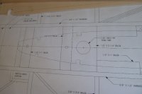
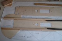
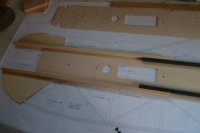
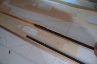
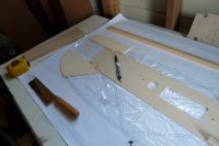
I took a day off from flying to start to lay one up.

Airplane specs;

Wingspan 80.5 inches
Length 79.75 inches
Wing Area 2030
Typical flying weight 16.5 to 18 pounds depending on accessories and building style.

Full kit consists of all the build plans, all CNC router cut ribs, CNC Router cut center fuse section- carbon fiber wing tube and wing tube receiver, fuse tubes, all sticks, sheeting, hardwood and firewall. This kit has all wood needed to complete the airframe. The wing is removable for transport to and from the flying field.
Also included is custom 3/16 6061 T-6 main landing gear, 3.5 inch aluminum lite wheels(spun aluminum hub and rubberized plastic tread , WWRC no break axles, 3/16 Robart hinges, Custom WWRC G-4 double truss control horns designed for this plane (less weight, strong enough to fly a 40%), stainless capture ends and carbon rods for all controls including throttle, dubro HD ball links (2 per control horn), SAE 4-40 socket head bolts, washers and fiber lock nuts (basically a keeper hardware package including throttle linkage)
 
P1010437(1).JPGP1010436(1).JPGWe start with the fuse center section.

The 1/8 inch ply center section (aka wing crutch area) has an interlocking tab to the lite ply tail section. There is a big and small tab so you can only lock them one way.

The way to tell which way is up is to engage the tabs and lay the center section over the plans... Up front the wing tube lnes up and the anti rotation pins line up but the real way to tell if you are right side up or upside down is the servo in the tail location.... It only will go one way.

Once I figure this out, I put a little arrow on both ply center sections so I cant goof up...

Photos show that there is a 3/8x1/2 balsa (rearward) box in the center section and 3/8x1/2 hardwood rail forward.

I used medium CA for the balsa that is rearward and will use epoxy for the hardwood rail which is forward.

We try to use as little CA forward of the CG on gassers because of the vibration encountered.
 

Attachments

  • P1010438(1).JPG
    P1010438(1).JPG
    132.6 KB · Views: 343
  • P1010432(1).JPG
    P1010432(1).JPG
    161.1 KB · Views: 314
  • P1010433(1).JPG
    P1010433(1).JPG
    150.8 KB · Views: 352
  • P1010435(1).JPG
    P1010435(1).JPG
    161.5 KB · Views: 297
Last edited by a moderator:
The tabs are tacked together with medium CA. There is no strength in them, but we want to lock them in for orientation.

Next the balsa 3/8x 1/2 inch sticks are set in the aft section. I put a mark on the lite ply wood where it stops up front and then use thick CA to glue them down... I follow up with medium ca to put a bead iin the balsa to lite ply 90 degree turn. No strength in single items... but when done, it is like an I beam in a building.... and very strong..
 

Attachments

  • P1010440(1).JPG
    P1010440(1).JPG
    143.8 KB · Views: 350
Last edited by a moderator:
Next glued in is the .505 fiberglass tube. I like to use gorilla glue on this item for the gap filling properties and also it is not brittle like ca. Once I clamp it in place and am waiting for the GG to expand, I run a bead of medium CA down the tube to insure it wont move while the CA is filling the gaps... plus I clamp it.

Note: The kit comes with 47 inch fuse tubes which give the majority of the rigidity in the tail section as the box construction. In the photo I have use one fused together with a splice which gives no added strength from the center section cut out mid airfoil but allow me to rout the servo wire to the throttle and an ignition wire to the ignition. Kits that leave her in the future kits will come with the added pieces of tube that a builder can choose to use up front to rout the wires.
 

Attachments

  • P1010441(1).JPG
    P1010441(1).JPG
    96.5 KB · Views: 319
  • P1010442(1).JPG
    P1010442(1).JPG
    119.7 KB · Views: 290
Last edited by a moderator:
That is it for tonight. In the morning when dry I will take the 1/4 inch wood dowel for a front and rear anti rotation pin and gently sand them so that they will fit both sides of the fuse center section (should have done this already). Tomorrow I glue in the center section bracing and the fun part is the epoxy to add the top half and that is where the anti rotation pins will help to guide me to keep both halves centered.

Once the center section is done, the fuse outline is mainly superficial and will go pretty quick.

I will continue to give insight on the build to make it as easy as possible... It really is easy... being a profile plane... but will take the hard flights too.
 
Top