JimD
50cc
With our giant scale planes, long servo extension cables, and high power servos with their high current demand...how can we make the connection between the wings and fuselage to minimize potential problems.
Like most modelers, we are always looking for a better more reliable way to do things. With our giant scale planes, the wing/fuselage connection was an area of interest. Having worked with the Sermos connectors on our crop of electric planes over the years, I got to thinking about using them for this job.
That took us on a search for Anderson Powerpole products: http://www.powerwerx.com/anderson-powerpoles/housings-contacts/
Turns out that the housing are available in a variety of colors and the metal pins are available in sizes down to small gauge wire. Since these connectors are designed to be plugged and unplugged through many, many cycles, and since they are rated for high current and low loss, seemed like a plausible idea.
So, we ordered red, black, white, and yellow housing, the small size connector pins, and four across mounting clamps. We also bought some bulk heavy gauge twisted servo wire in Futaba and Hitec colors from Servo City. Since we are using Hitec servos with the twisted wire leads, the twisted servo wire just looks right! We also bought some unassembled Hitec gold plated male connectors to finish out our connections on the receiver side.
https://www.servocity.com/html/wire_connectors___access_.html
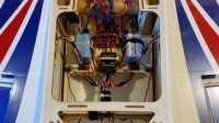
We used the red/black/white for the aileron servos and the red/black/yellow for the flap servos. The red and black wires were combined in the same connector pin assembly using the corresponding color housing. The yellow signal wire and the white signal wire each got their own connector pairs and matching housings. Makes it easy to trace which lead goes to which servo when you get to the receiver end of the cables.
The Hitec connectors were added to the receiver end of the cables using the wire stripper and pin crimper sold by Hansen Hobbies:
http://hansenhobbies.com/products/connectors/tools/
We have used this setup in two planes over two flying seasons with excellent results.
Here is a photo essay of the process:


Like most modelers, we are always looking for a better more reliable way to do things. With our giant scale planes, the wing/fuselage connection was an area of interest. Having worked with the Sermos connectors on our crop of electric planes over the years, I got to thinking about using them for this job.
That took us on a search for Anderson Powerpole products: http://www.powerwerx.com/anderson-powerpoles/housings-contacts/
Turns out that the housing are available in a variety of colors and the metal pins are available in sizes down to small gauge wire. Since these connectors are designed to be plugged and unplugged through many, many cycles, and since they are rated for high current and low loss, seemed like a plausible idea.
So, we ordered red, black, white, and yellow housing, the small size connector pins, and four across mounting clamps. We also bought some bulk heavy gauge twisted servo wire in Futaba and Hitec colors from Servo City. Since we are using Hitec servos with the twisted wire leads, the twisted servo wire just looks right! We also bought some unassembled Hitec gold plated male connectors to finish out our connections on the receiver side.
https://www.servocity.com/html/wire_connectors___access_.html
We used the red/black/white for the aileron servos and the red/black/yellow for the flap servos. The red and black wires were combined in the same connector pin assembly using the corresponding color housing. The yellow signal wire and the white signal wire each got their own connector pairs and matching housings. Makes it easy to trace which lead goes to which servo when you get to the receiver end of the cables.
The Hitec connectors were added to the receiver end of the cables using the wire stripper and pin crimper sold by Hansen Hobbies:
http://hansenhobbies.com/products/connectors/tools/
We have used this setup in two planes over two flying seasons with excellent results.
Here is a photo essay of the process:
")