• If you are new to GiantScaleNews.com, please register, introduce yourself, and make yourself at home.

    We're 1st in Giant Scale RC because we've got the best membership on the internet! Take a look around and don't forget to register to get all of the benefits of GSN membership!

    Welcome!

Scale Don Smith P-51 Mustang

stangflyer

I like 'em "BIG"!
Next set of photos...These span from Dec. 22 thru to Dec. 25.
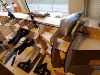
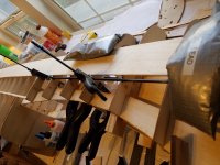
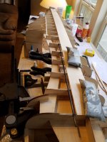
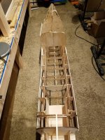
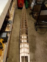
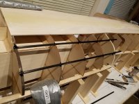
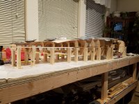
Supporting the middle of the formers while I add the carbon rods on the opposite side of the fuse.
20181222_122902.jpg 20181222_122909.jpg 20181222_122914.jpg
Once the carbon rods were in place, I could continue building the other side of the engine box.
20181222_124136.jpg
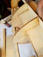
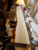
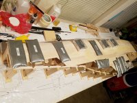
And start adding some sheeting…
20181222_131545.jpg 20181222_151630.jpg 20181222_152011.jpg
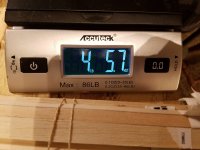
At this point I've gained just over half a pound.
20181222_180620.jpg
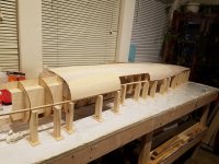
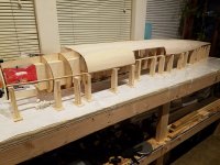
I am very pleased with the progress and the straightness of the fuse at it stands right now.

20181222_180741.jpg 20181222_180806.jpg
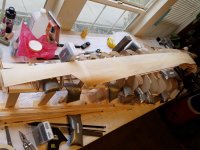
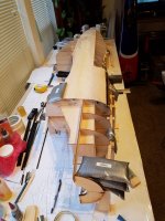
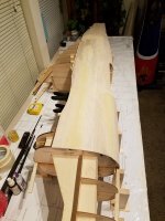
Next, sheeting across the forward section of the fuse.
and continuing on along the side.

20181222_191854.jpg 20181223_141050.jpg 20181223_202046.jpg 20181223_202054.jpg 20181223_202100.jpg 20181223_202103.jpg 20181223_211933.jpg 20181223_212033.jpg 20181223_212123.jpg
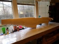
She is starting to look like a real Mustang fuse now.
20181224_134321.jpg
Time to start figuring out how to get that silly tail gear structure built.
20181225_190627.jpg 20181225_190636.jpg

More to come....
 
Last edited:

stangflyer

I like 'em "BIG"!
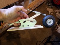
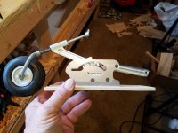
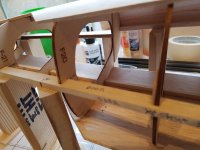
Photos from Dec. 26 and 27. This tail gear structure was not really difficult. Just took a little time to figure out how to approach it. I knew I needed solid support for the Sierra gear. I knew also I needed that structure to be light. I just do not want any tail weight on this bird. So this is what I came up with.

I first took from the plans where the tail gear doors are supposed to be located. Not sure this will stay exact, but should be very close.
20181226_124322.jpg 20181226_124325.jpg
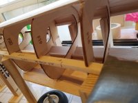
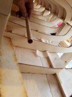
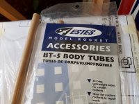
I also decided that I did not want to run my retract air lines and servo leads in "open air" down the middle of the fuse cavity. So I snagged a bag of model rocket tubes from my son. I plan to attach them to the insides of the formers of the fuse to run the air lines and servo leads through. They are light enough and actually will add strength to the sides of the fuse formers.
20181226_124339.jpg
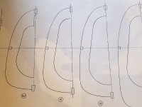
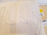
From the DS plans, I traced the required fuse formers so that I could make lite ply doublers for the tail gear to be supported on.

20181226_124430.jpg 20181226_124437.jpg

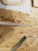
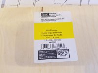
I bought a sheet of 1/8" Birch ply for this step.
20181226_124455.jpg
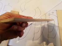
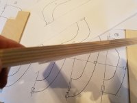
I also was not sure if I needed to use a 1/2" plate for the tail gear to rest on or if a simple 1/4" would be strong enough. I'll decide this later after the fuse tubes.
20181226_124538.jpg 20181226_124544.jpg
Estes makes some good stuff. And not just for rockets. LOL
20181226_124619.jpg
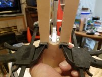
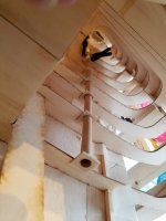
I cut (14) 1"x1" 3/32" light ply tube supports to run the fuse tubes through. Instead of just laying them on the formers then gluing them in place, I used my Dremel to grind a "pocket" for the tubes to rest in then put the supports in place and glued the entire structure in as a unit. Yes, talk about increased side load strength and overall former strength. Wow...very impressive.
20181226_154507.jpg 20181226_155037.jpg
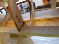
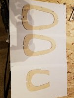
These are the fuse former doublers I cut to be placed at F18, F19 and F20 to support the tail gear. Later I decided to change the location of the gear to keep it as scale as possible. This would include adding a doubler to F21 as well.
20181226_202432.jpg
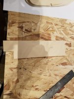
I ultimately decided on the 1/4" ply plate for the gear support plate.
20181226_204428.jpg 20181226_204435.jpg
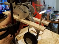
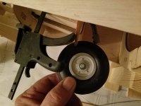
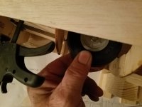
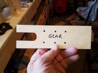
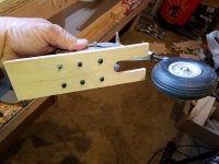
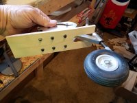
Making a "mock up" plate for the gear.
20181226_212811.jpg 20181226_212821.jpg 20181226_212847.jpg
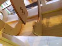
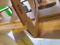
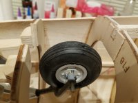
To enable the tail gear to be in the proper scale location and to allow it to retract, it was necessary to remove a portion of F19. 20181227_002637.jpg 20181227_002643.jpg 20181227_002656.jpg
So far my trail fit is good. But not as I really want so a little modification will need to be done.
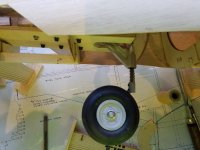
Ok, I am good with this. I have ample clearance on F18 and I am also getting a full extension/retraction of the gear without contacting any structure.
20181227_002727.jpg 20181227_002730.jpg 20181227_002733.jpg 20181227_002738.jpg

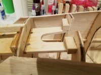
This is the final revised gear plate to go inside the tail structure of the Mustang.

20181227_130818.jpg 20181227_130824.jpg 20181227_132051.jpg 20181227_132059.jpg

I had planned to use simple rails for the tail gear to bolt to. But I really wanted much more strength for the gear as well as side load on the fuse. So...this is what will be used.
20181227_132108.jpg 20181227_132113.jpg 20181227_132123.jpg

So now it is time to get those doublers glued in place and set the tail gear plate into place.
20181227_132415.jpg 20181227_132427.jpg 20181227_132431.jpg 20181227_132437.jpg
I like the location and it looks like it is going to work great.
20181227_132530.jpg 20181227_132547.jpg 20181227_132610.jpg 20181227_132621.jpg Before permanently gluing in the tail gear structure, I decided it would be a good time to get the remaining fuse tube glued in place.
20181227_150049.jpg 20181227_150110.jpg
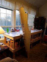
A shot of the nearly completed fuse while it stands on its tail waiting for glue to cure.
20181227_155248.jpg
Back to the tail gear installation...
20181227_172304.jpg
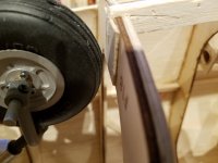
Good clearance so it is time to epoxy in the plate.
20181227_191212.jpg 20181227_191214.jpg
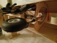
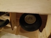
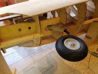
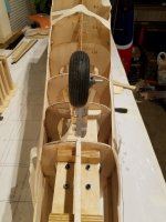
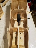
Full extension of the gear...
20181227_193057.jpg
Half way retracted...
20181227_193104.jpg
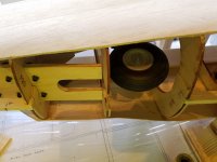
Full retraction of the tail gear...
20181227_193110.jpg
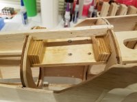
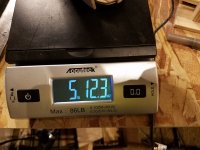
And the best part? Only about one and a half pounds added..."WITH" the tail gear installed.
20181227_194336.jpg
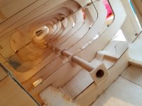
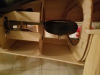
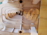
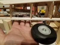
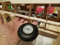
A look down the inside of the fuse with the tail gear extended...
20181227_195706.jpg
A look with the gear fully retracted...
20181227_195744.jpg

The fuse is really coming along and it is pretty strong as it stands. I am a little worried however of the weight of the Kolm 150 that will be powering this bird. If the plane were being built to support the intended engine choice... A G62 or like, then I would not worry not one bit. Even a 3w 110cs or like would be fine. But anything of more weight bothers me. This is the main reason I added the carbon rods to the fuse. The way they are designed and implemented, they should support the front of the fuse clear back to behind the location of the main landing gear. Which equates to the main gear and the structure throughout supporting the weight of the Kolm. Hopefully, it will work out as I have engineered it to. Guess we will see when I get to the point of installing the 150. Yes, the thought of not using the Kolm has crossed my mind.

I wanted to stay at or under 8 pounds on the fuse when fully constructed. I really think I am going to make it. I have also done a lot..."A LOT" of research on glassing technics and what not. I was very afraid at first of adding too much weight. But really hated the idea of using a plastic covering such as Ultracote on the big Stang. From what I have been seeing so far, glassing will not add any more weight than simple covering. I was also afraid of glassing as I have never done it before. But also from what I am seeing, it is almost as easy as laying out and ironing on covering. So... glassing it will be. Plus, it will add a ton of strength to the fuse. Especially in the nose where I will need it for the Kolm 150.

More to come fellas....But not today.
 

acerc

640cc Uber Pimp
Speechless! Almost. lol.. Everything is looking great and me thinks your worrying to much about that motors weight.
A bit of a heads up on the laser. Being a cross and most importantly, self leveling, be careful setting up and using it. With self leveling your plane will need to be level front to back and side to side, not just sitting on a flat surface, basically the laser is built for 2D where as your going to be using it in 3D. So just double check the airframes position in regards to the lasers path.
 
Last edited:

Snoopy1

640cc Uber Pimp
Speechless! Almost. lol.. Everything is looking great and me thinks your worrying to much about that motors weight.
A bit of a heads up on the laser. Being a cross and most importantly, self leveling, be careful setting up and using it. With self leveling your plane will need to be level front to back and side to side, not just sitting on a flat surface, basically the laser is built for 2D where as your going to be using it in 3D. So just double check the airframes position in regards to the lasers path.
How true about the lasers they will get you into trouble I have stoped using it in the self leveling modes. Always use it locked and set it up from one of the planes axis.
 

Snoopy1

640cc Uber Pimp
Photos from Dec. 26 and 27. This tail gear structure was not really difficult. Just took a little time to figure out how to approach it. I knew I needed solid support for the Sierra gear. I knew also I needed that structure to be light. I just do not want any tail weight on this bird. So this is what I came up with.

I first took from the plans where the tail gear doors are supposed to be located. Not sure this will stay exact, but should be very close.
View attachment 107785 View attachment 107786
I also decided that I did not want to run my retract air lines and servo leads in "open air" down the middle of the fuse cavity. So I snagged a bag of model rocket tubes from my son. I plan to attach them to the insides of the formers of the fuse to run the air lines and servo leads through. They are light enough and actually will add strength to the sides of the fuse formers.
View attachment 107787
From the DS plans, I traced the required fuse formers so that I could make lite ply doublers for the tail gear to be supported on.
View attachment 107788 View attachment 107789

I bought a sheet of 1/8" Birch ply for this step.
View attachment 107790
I also was not sure if I needed to use a 1/2" plate for the tail gear to rest on or if a simple 1/4" would be strong enough. I'll decide this later after the fuse tubes.
View attachment 107791 View attachment 107792
Estes makes some good stuff. And not just for rockets. LOL
View attachment 107793
I cut (14) 1"x1" 3/32" light ply tube supports to run the fuse tubes through. Instead of just laying them on the formers then gluing them in place, I used my Dremel to grind a "pocket" for the tubes to rest in then put the supports in place and glued the entire structure in as a unit. Yes, talk about increased side load strength and overall former strength. Wow...very impressive.
View attachment 107794 View attachment 107795
These are the fuse former doublers I cut to be placed at F18, F19 and F20 to support the tail gear. Later I decided to change the location of the gear to keep it as scale as possible. This would include adding a doubler to F21 as well.
View attachment 107796
I ultimately decided on the 1/4" ply plate for the gear support plate.
View attachment 107797 View attachment 107798
Making a "mock up" plate for the gear.
View attachment 107799 View attachment 107800 View attachment 107801
To enable the tail gear to be in the proper scale location and to allow it to retract, it was necessary to remove a portion of F19. View attachment 107802 View attachment 107803 View attachment 107804
So far my trail fit is good. But not as I really want so a little modification will need to be done.
Ok, I am good with this. I have ample clearance on F18 and I am also getting a full extension/retraction of the gear without contacting any structure.
View attachment 107805 View attachment 107806 View attachment 107807 View attachment 107808

This is the final revised gear plate to go inside the tail structure of the Mustang.

View attachment 107809 View attachment 107810 View attachment 107811 View attachment 107812

I had planned to use simple rails for the tail gear to bolt to. But I really wanted much more strength for the gear as well as side load on the fuse. So...this is what will be used.
View attachment 107813 View attachment 107814 View attachment 107815

So now it is time to get those doublers glued in place and set the tail gear plate into place.
View attachment 107816 View attachment 107817 View attachment 107818 View attachment 107819
I like the location and it looks like it is going to work great.
View attachment 107820 View attachment 107821 View attachment 107822 View attachment 107823 Before permanently gluing in the tail gear structure, I decided it would be a good time to get the remaining fuse tube glued in place.
View attachment 107824 View attachment 107825
A shot of the nearly completed fuse while it stands on its tail waiting for glue to cure.
View attachment 107826
Back to the tail gear installation...
View attachment 107827
Good clearance so it is time to epoxy in the plate.
View attachment 107828 View attachment 107829
Full extension of the gear...
View attachment 107830
Half way retracted...
View attachment 107831
Full retraction of the tail gear...
View attachment 107832
And the best part? Only about one and a half pounds added..."WITH" the tail gear installed.
View attachment 107833
A look down the inside of the fuse with the tail gear extended...
View attachment 107834
A look with the gear fully retracted...
View attachment 107835

The fuse is really coming along and it is pretty strong as it stands. I am a little worried however of the weight of the Kolm 150 that will be powering this bird. If the plane were being built to support the intended engine choice... A G62 or like, then I would not worry not one bit. Even a 3w 110cs or like would be fine. But anything of more weight bothers me. This is the main reason I added the carbon rods to the fuse. The way they are designed and implemented, they should support the front of the fuse clear back to behind the location of the main landing gear. Which equates to the main gear and the structure throughout supporting the weight of the Kolm. Hopefully, it will work out as I have engineered it to. Guess we will see when I get to the point of installing the 150. Yes, the thought of not using the Kolm has crossed my mind.

I wanted to stay at or under 8 pounds on the fuse when fully constructed. I really think I am going to make it. I have also done a lot..."A LOT" of research on glassing technics and what not. I was very afraid at first of adding too much weight. But really hated the idea of using a plastic covering such as Ultracote on the big Stang. From what I have been seeing so far, glassing will not add any more weight than simple covering. I was also afraid of glassing as I have never done it before. But also from what I am seeing, it is almost as easy as laying out and ironing on covering. So... glassing it will be. Plus, it will add a ton of strength to the fuse. Especially in the nose where I will need it for the Kolm 150.

More to come fellas....But not today.

I am enjoying this one. Man that is quiet the undertaking. I could never build two at one time especially a plane as complicated as the mustang. Take your time and enjoy it. It will be done when it is done, this not a normal build and not likely to build another for a while.
And by the way great job.
 
Last edited:

dhal22

GSN Sponsor Tier 1
Photos from Dec. 26 and 27. This tail gear structure was not really difficult. Just took a little time to figure out how to approach it. I knew I needed solid support for the Sierra gear. I knew also I needed that structure to be light. I just do not want any tail weight on this bird. So this is what I came up with.

I first took from the plans where the tail gear doors are supposed to be located. Not sure this will stay exact, but should be very close.
View attachment 107785 View attachment 107786
I also decided that I did not want to run my retract air lines and servo leads in "open air" down the middle of the fuse cavity. So I snagged a bag of model rocket tubes from my son. I plan to attach them to the insides of the formers of the fuse to run the air lines and servo leads through. They are light enough and actually will add strength to the sides of the fuse formers.
View attachment 107787
From the DS plans, I traced the required fuse formers so that I could make lite ply doublers for the tail gear to be supported on.

View attachment 107788 View attachment 107789

I bought a sheet of 1/8" Birch ply for this step.
View attachment 107790
I also was not sure if I needed to use a 1/2" plate for the tail gear to rest on or if a simple 1/4" would be strong enough. I'll decide this later after the fuse tubes.
View attachment 107791 View attachment 107792
Estes makes some good stuff. And not just for rockets. LOL
View attachment 107793
I cut (14) 1"x1" 3/32" light ply tube supports to run the fuse tubes through. Instead of just laying them on the formers then gluing them in place, I used my Dremel to grind a "pocket" for the tubes to rest in then put the supports in place and glued the entire structure in as a unit. Yes, talk about increased side load strength and overall former strength. Wow...very impressive.
View attachment 107794 View attachment 107795
These are the fuse former doublers I cut to be placed at F18, F19 and F20 to support the tail gear. Later I decided to change the location of the gear to keep it as scale as possible. This would include adding a doubler to F21 as well.
View attachment 107796
I ultimately decided on the 1/4" ply plate for the gear support plate.
View attachment 107797 View attachment 107798
Making a "mock up" plate for the gear.
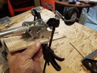
View attachment 107799 View attachment 107800 View attachment 107801
To enable the tail gear to be in the proper scale location and to allow it to retract, it was necessary to remove a portion of F19. View attachment 107802 View attachment 107803 View attachment 107804
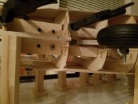
So far my trail fit is good. But not as I really want so a little modification will need to be done.
Ok, I am good with this. I have ample clearance on F18 and I am also getting a full extension/retraction of the gear without contacting any structure.
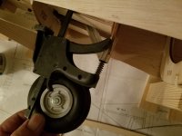
View attachment 107805 View attachment 107806 View attachment 107807 View attachment 107808

This is the final revised gear plate to go inside the tail structure of the Mustang.
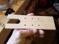
View attachment 107809 View attachment 107810 View attachment 107811 View attachment 107812

I had planned to use simple rails for the tail gear to bolt to. But I really wanted much more strength for the gear as well as side load on the fuse. So...this is what will be used.
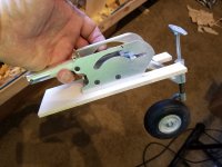
View attachment 107813 View attachment 107814 View attachment 107815

So now it is time to get those doublers glued in place and set the tail gear plate into place.
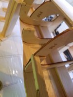
View attachment 107816 View attachment 107817 View attachment 107818 View attachment 107819
I like the location and it looks like it is going to work great.
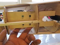
View attachment 107820 View attachment 107821 View attachment 107822 View attachment 107823 Before permanently gluing in the tail gear structure, I decided it would be a good time to get the remaining fuse tube glued in place.
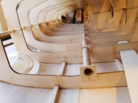
View attachment 107824 View attachment 107825
A shot of the nearly completed fuse while it stands on its tail waiting for glue to cure.
View attachment 107826
Back to the tail gear installation...
View attachment 107827
Good clearance so it is time to epoxy in the plate.
View attachment 107828 View attachment 107829
Full extension of the gear...
View attachment 107830
Half way retracted...
View attachment 107831
Full retraction of the tail gear...
View attachment 107832
And the best part? Only about one and a half pounds added..."WITH" the tail gear installed.
View attachment 107833
A look down the inside of the fuse with the tail gear extended...
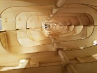
View attachment 107834
A look with the gear fully retracted...
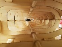
View attachment 107835

The fuse is really coming along and it is pretty strong as it stands. I am a little worried however of the weight of the Kolm 150 that will be powering this bird. If the plane were being built to support the intended engine choice... A G62 or like, then I would not worry not one bit. Even a 3w 110cs or like would be fine. But anything of more weight bothers me. This is the main reason I added the carbon rods to the fuse. The way they are designed and implemented, they should support the front of the fuse clear back to behind the location of the main landing gear. Which equates to the main gear and the structure throughout supporting the weight of the Kolm. Hopefully, it will work out as I have engineered it to. Guess we will see when I get to the point of installing the 150. Yes, the thought of not using the Kolm has crossed my mind.

I wanted to stay at or under 8 pounds on the fuse when fully constructed. I really think I am going to make it. I have also done a lot..."A LOT" of research on glassing technics and what not. I was very afraid at first of adding too much weight. But really hated the idea of using a plastic covering such as Ultracote on the big Stang. From what I have been seeing so far, glassing will not add any more weight than simple covering. I was also afraid of glassing as I have never done it before. But also from what I am seeing, it is almost as easy as laying out and ironing on covering. So... glassing it will be. Plus, it will add a ton of strength to the fuse. Especially in the nose where I will need it for the Kolm 150.

More to come fellas....But not today.


.

Jeeze............................
 

stangflyer

I like 'em "BIG"!
Speechless! Almost. lol.. Everything is looking great and me thinks your worrying to much about that motors weight.
A bit of a heads up on the laser. Being a cross and most importantly, self leveling, be careful setting up and using it. With self leveling your plane will need to be level front to back and side to side, not just sitting on a flat surface, basically the laser is built for 2D where as your going to be using it in 3D. So just double check the airframes position in regards to the lasers path.

How true about the lasers they will get you into trouble I have stoped using it in the self leveling modes. Always use it locked and set it up from one of the planes axis.

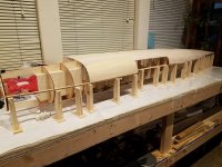
Thanks for the input fellas. I am very appreciative you took the time to give me some advice. I have not used a laser for an airframe before. I will probably set the fuse perfectly straight then use the laser for the tail surfaces only. I am going to be very cautious with this step.
 

WMcNabb

150cc
First of all, really enjoy seeing the progress and appreciate the time you’re taking to document your thought process!

As far as the laser, I’m using the same Bosch model you are, and simply leveling the airplane in whichever direction before applying the laser to it. Only one problem, now I can’t seem to do anything without using it.

A079E0D6-8BAB-4B18-BCC9-0673C839CBB3.jpeg
 

stangflyer

I like 'em "BIG"!
First of all, really enjoy seeing the progress and appreciate the time you’re taking to document your thought process!

As far as the laser, I’m using the same Bosch model you are, and simply leveling the airplane in whichever direction before applying the laser to it. Only one problem, now I can’t seem to do anything without using it.

View attachment 107847
Perfect! That is what I was needing. Some accurate input on proper usage. Thanks brother.
 
Top