• If you are new to GiantScaleNews.com, please register, introduce yourself, and make yourself at home.

    We're 1st in Giant Scale RC because we've got the best membership on the internet! Take a look around and don't forget to register to get all of the benefits of GSN membership!

    Welcome!

Fiber Optic servo extension

stangflyer

I like 'em "BIG"!
I don't think I understand something. If for example on a wing that uses 3 servos for an aileron, does this require a battery for each servo? Which would mean an encoder and decoder for each servo? Maybe I missed this part!?!
 
I don't think I understand something. If for example on a wing that uses 3 servos for an aileron, does this require a battery for each servo? Which would mean an encoder and decoder for each servo? Maybe I missed this part!?!
My apologies for not explaining this part properly and a very good question.

You need one encoder and one decoder for each channel, but in the case of 3 servos per aileron , you can either use 3 encoder/decoder which is 3 channels or simply Y connect which is not my recommendation.
So look at it as simply a servo extension to be used on all channels to keep the receiver totally isolated from the servos.
Now as for the battery/ies, you would use One large battery for all servos or if you prefer to use two , then so bit it. but the rx gets its own battery which can be as little as 500 ma but I use 1000 ma lipo, and Lipo is not the driving force here , voltage is so you can use any chemical battery you want . if you use HV servos, not a problem with 2s lipos. same with the rx , if you use two rxs you can power both with one 1000 ma lipo.

If this is not clear , by all means let me know, remember I was a Robotics engineer, not a teacher so explaining things was not my forte lol

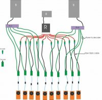
For all my own installations, I use one rx only, one small rx battery and one larger servo battery, I made a power bus to plug in the servo/decoder power
 

stangflyer

I like 'em "BIG"!
No "Y's" for this boy. If there simply is not an option, I will seek other alternatives. So example: 3 servo wing gets an encoder and decoder per channel... a fiber optic cable per channel, (servo) Then one large battery per set of three servos? Or would you use one huge battery to power the other wing, elevators and rudder as well?
 
No "Y's" for this boy. If there simply is not an option, I will seek other alternatives. So example: 3 servo wing gets an encoder and decoder per channel... a fiber optic cable per channel, (servo) Then one large battery per set of three servos? Or would you use one huge battery to power the other wing, elevators and rudder as well?
no Y's one channel for each servos . so for instance, 6 channels for ailerons, 1 for rudder if one servo is used, 2 for elevators if two servos used and 1 for throttle.
Assuming this is what you have, then 10 channels , 10 fiber optic servos extensions. one smallish battery for the receiver, one large battery for all the servos.
I can draw you a diagram if you wish,
As for servo battery, if you prefer two batteries for redundancy as such, then that is no problem.
 

stangflyer

I like 'em "BIG"!
That was actually my next question. I absolutely will not do anything above 50cc without redundancy. I'm certain many feel I way over power my systems. (2) 5200 7.4 LiIon for 100cc up. But...in my defense I've never ever lost a plane due to lack of battery power. I take that back. I lost my first beloved Cherokee 26 years ago due to a failed single brand new Nicd 6.0 volt battery. A cell went flat and reversed the remaining 4 cells. I recently did a stress test on the twin 5200's in my 260. Starting their 5th season and according to my records from new to now, I've lost about 6% of new original capacity. How would you go about setting up redundant power with your system?
 

WMcNabb

150cc
Roger, thanks for taking the time to explain your installation. If you wouldn't mind answering another question, being a fan of the Spektrum Powersafe receivers, I'm trying to envision how the setup is physically implemented.

From your photo at the beginning of the thread it appears that battery power is going to the encoder as well as the servo itself. If the battery is in the fuselage, two pathways would be needed for each servo? The decoder, fiber optic cable, encoder, and a separate power lead? Or only the fiber optic path where power and signal are together?

image.jpeg
 
On the image I drew up in corel draw, things might look a bit cluttered, in proper installation, its a different story.
Stangflyer you can see how I would do it for power redundancy.
WMcNabb, now you are able to see better where the receiver and servos are powered by different batteries
 

Attachments

  • Graphic1.jpg
    Graphic1.jpg
    56.1 KB · Views: 334

stangflyer

I like 'em "BIG"!
On the image I drew up in corel draw, things might look a bit cluttered, in proper installation, its a different story.
Stangflyer you can see how I would do it for power redundancy.
WMcNabb, now you are able to see better where the receiver and servos are powered by different batteries
Yes, thank you very much for taking the time to help us understand this system. Your drawing cleared about 99% of the clouds. I am still confused by one thing. And I do apologize for this if you've covered it. The receiver is sending signal and power to each servo. However the individual "Servo Batteries" are supplying the actual voltage. Where does the supplied voltage from the receiver terminate? At the encoder?
 
Yes, thank you very much for taking the time to help us understand this system. Your drawing cleared about 99% of the clouds. I am still confused by one thing. And I do apologize for this if you've covered it. The receiver is sending signal and power to each servo. However the individual "Servo Batteries" are supplying the actual voltage. Where does the supplied voltage from the receiver terminate? At the encoder?
no apologies please , the more questions you ask the more other people will benefit.
The receiver is sending the signal only to the servos not the power , the power out of the receiver stops at the encoder, , the decoders will have there power from the larger batteries, , the number of battery redundancy depends on you.
 

acerc

640cc Uber Pimp
If I understand correctly the black line from the batteries is representing positive and negative. The Rx is powered by the center battery and the servos by the outer batteries. The red line from Rx is signal only and the green power to decoder is representing positive and negative. So the servos are powered by the outer batteries via the decoder system, Rx signal via the decoder system, the Rx has no power exiting leaving no path for RF to enter.
 
Last edited:
Top