GSNadmin
Staff member
In the last print issue of Fly RC (April 2017), we got to talk about the Paul K. Guillow Company, examining what they have done as part of the history of American aeromodelling and what they have to offer you today if you are interested in building model airplanes using balsa and various other materials that work well with it. Building model airplanes is what Master’s Workshop has been about since the beginning and that’s the way it’s going to remain. I have chosen to concentrate on Guillow’s kits because they seem to be everywhere you look. The modelers who have built one “stock” (or tried) as well as those who want to learn how to do a practical RC conversion of just about any of them are pretty well beyond counting. I suspect that last month I left you with more questions than answers while talking about the two Kit No. 403 Spitfires I’ve been experimenting with. This is the part where we get to those answers and we’ll do it in the usual Master’s Workshop style … patiently, with plenty of detail.
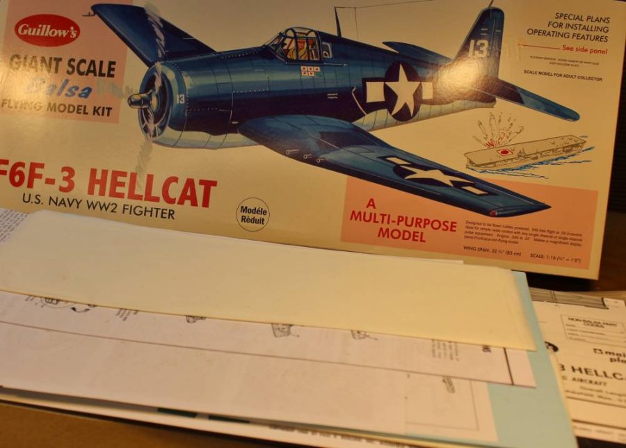
Wanna’ build a Hellcat? The box cover art Guillow’s has created for their entire line of balsa scale model airplane kits…all of which are Made in America … makes it hard to say no. Let’s talk about all those various kits for a moment. All Guillow’s kits on the market today are presented as stick-and-tissue “flying” models designed for rubber-powered free flight. Some of them, especially the few “non-scale” designs, can realistically be expected to fly that way. Most of the rest show a traditional rubber power prop setup on the plan and with the proper application of model building skill and patience they can be made to fly that way. Some of the more advanced/complex kits are advertised as “non-flying, display-only” models, but those still use the stick-and-tissue approach to design. In fact most of those display kits can be just as successfully converted to electric powered RC as can nearly all of the “flying” jobs. Some of these, like the 400 Series from which last month’s Spitfires come require lots of modification like figuring out working control surfaces as well as a custom RC installation. Others, like the 1000 Series which includes this Hellcat are larger and more complex and already include provision for working controls, which makes practical RC conversion easier. Our Hellcat is a good representation of this part of the Guillow’s line, which is why I have chosen it as our lead-off project. What we are going to do with it is to make those scale control surfaces work, add an appropriate electric motor, ESC and LiPo battery pack, and redesign/replace the original landing gear (with retracts in this case) with something that will survive real-world operations. In addition we are going to explore using several interesting alternative building techniques to improve the exterior surfaces in terms of both appearance and durability. Let’s get on with some model building and I’ll explain each of these modifications as we go along.
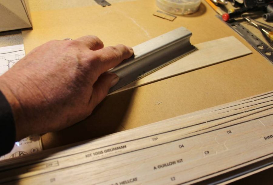
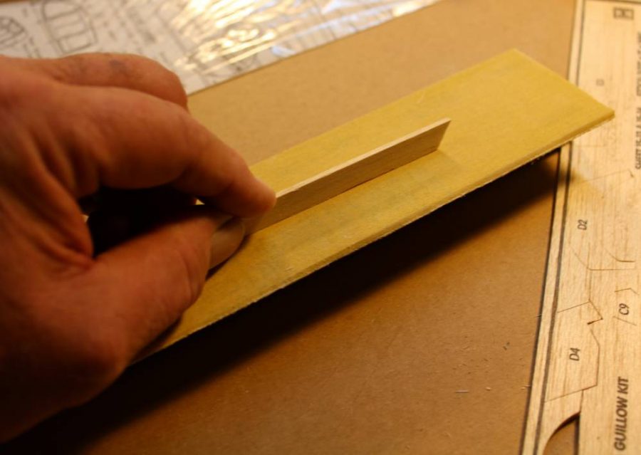
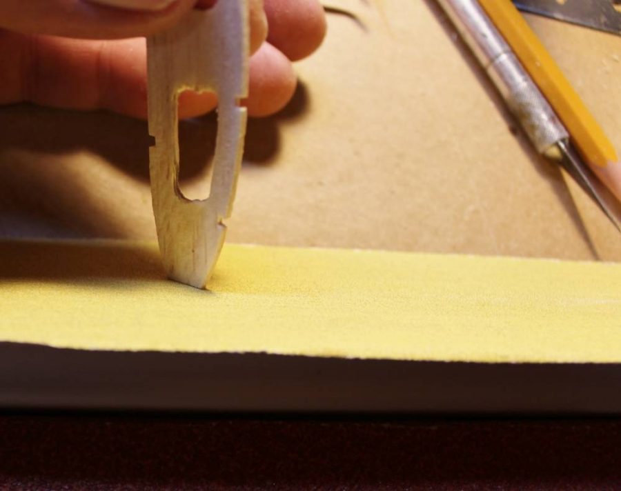
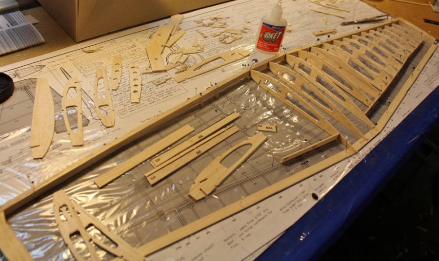
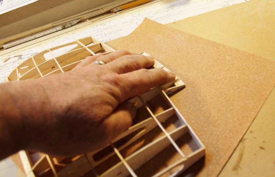
Let’s begin by getting down to the real basics … what to with all those balsa parts. Some of the “conversion-friendly” kits (like those Kit No. 403 Spitfires) have been upgraded to laser cutting. The Hellcat is not one of these…it depends on the time-honored (and less than perfect) process of die cutting. We have already talked a lot about this. Right now I’m showing you one of the best ways to deal with die-cut parts sheets that may be rough, slightly heavier than you’d like, and not fully cut-through. We are going to sand down the back of each sheet to get a smoother surface, get rid of any excess thickness/weight we don’t really need, and free up any and all incomplete cuts from the back side, which is where the dies may have failed to reach. How much of this you may need to do will vary from one kit to the next. With this Hellcat I chose to use a 220-grit sander to take off about 1/64” of balsa.
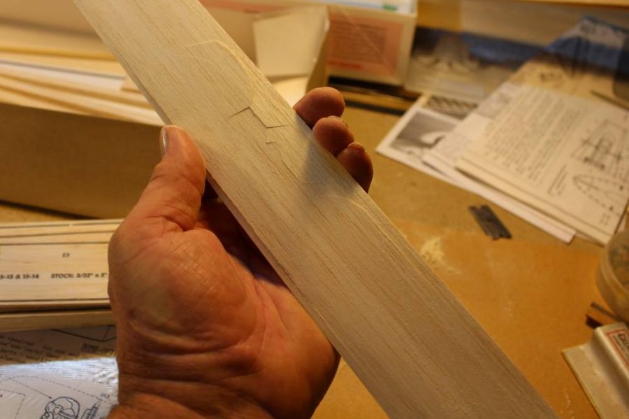
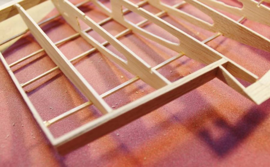
This is the result. The surface of the balsa is really smooth, and most important, the shallow die cuts have been corrected so the various parts are nearly ready to fall out on their own.
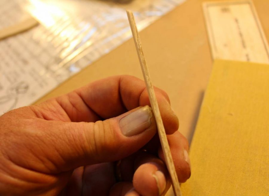
Die-cut balsa parts, unlike their laser-cut cousins, are by definition going to be less consistently accurate. This is true for just about any die-cut kit, not just Guillow’s. This is one of the horizontal tail outline parts as it came out of the sheet … can you see the rough edge?
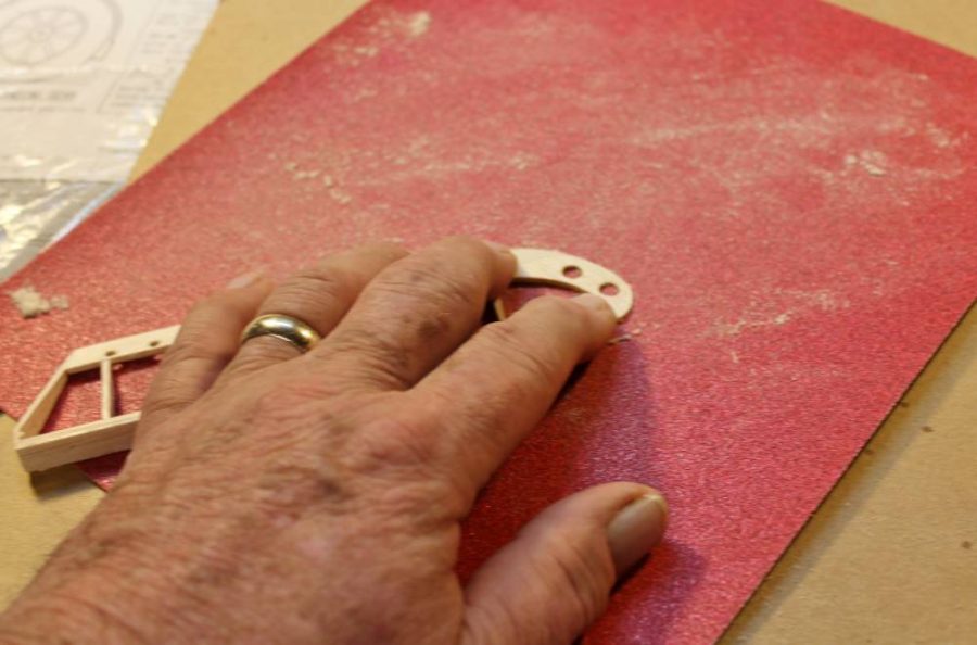
You could assemble it as-is, but you shouldn’t. That roughness equates to extra weight, poor parts fit and degraded glue joint strength as a result of the loose joint caused by that roughness. The 320-grit sanding block is the fix for all of that.
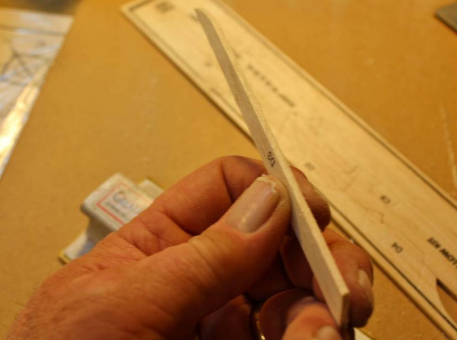
See the nice smooth, crisp edge that results from a minute or so of extra care? This is one of those old-timer model building “secrets” that you have to want to learn about to do this stuff right.
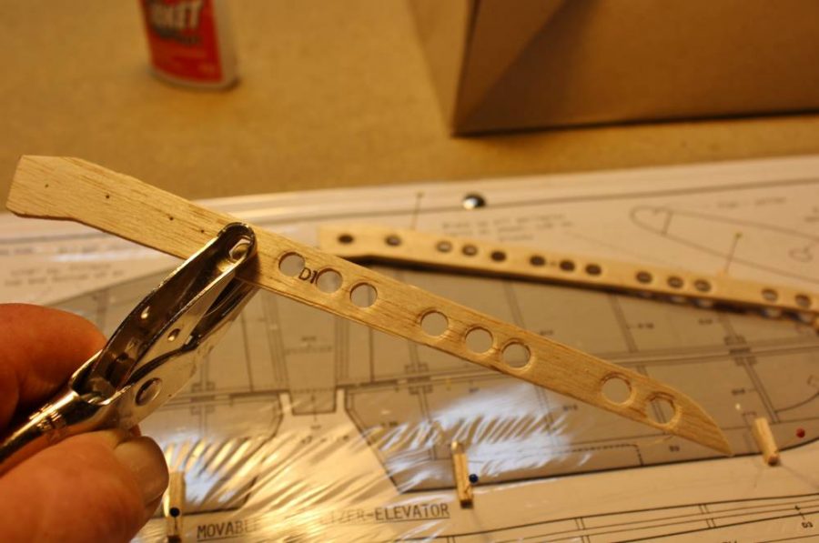
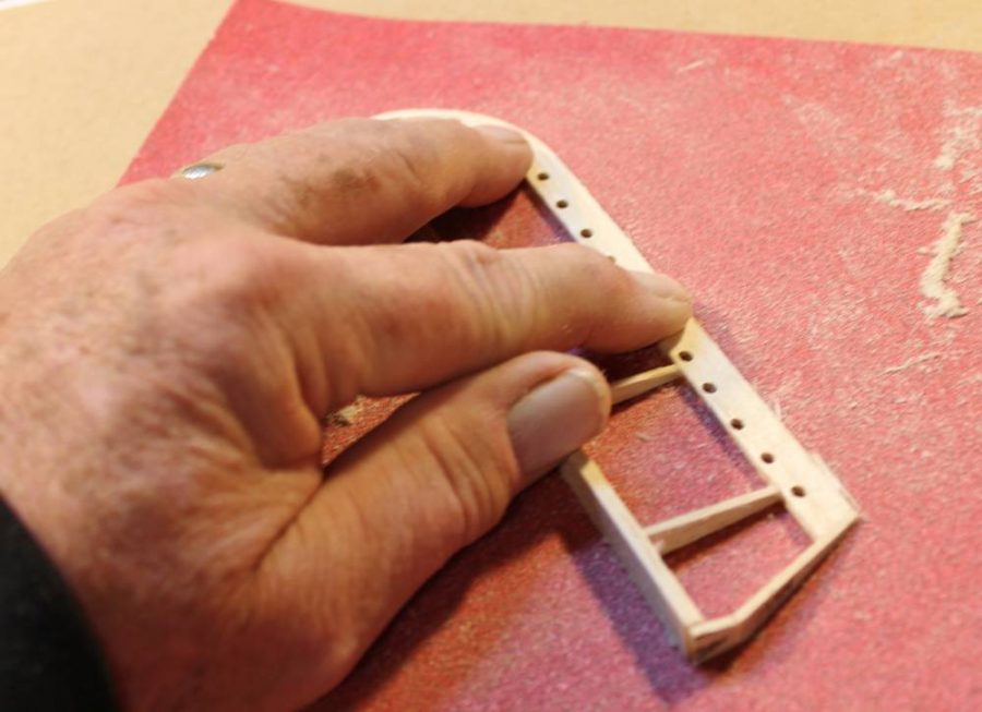
I’m not sure whether this is “old time” or not…I have never seen anyone else do this. An ordinary ¼” paper punch will make clean holes through soft to medium balsa sheet up to about 3/32” thick. Removing weight from the tail of any model is a good idea if you can do it without compromising structural integrity. These edge parts are going to get some serious reinforcement before long that will work in concert with the lightening holes…watch for what I’m going to do.
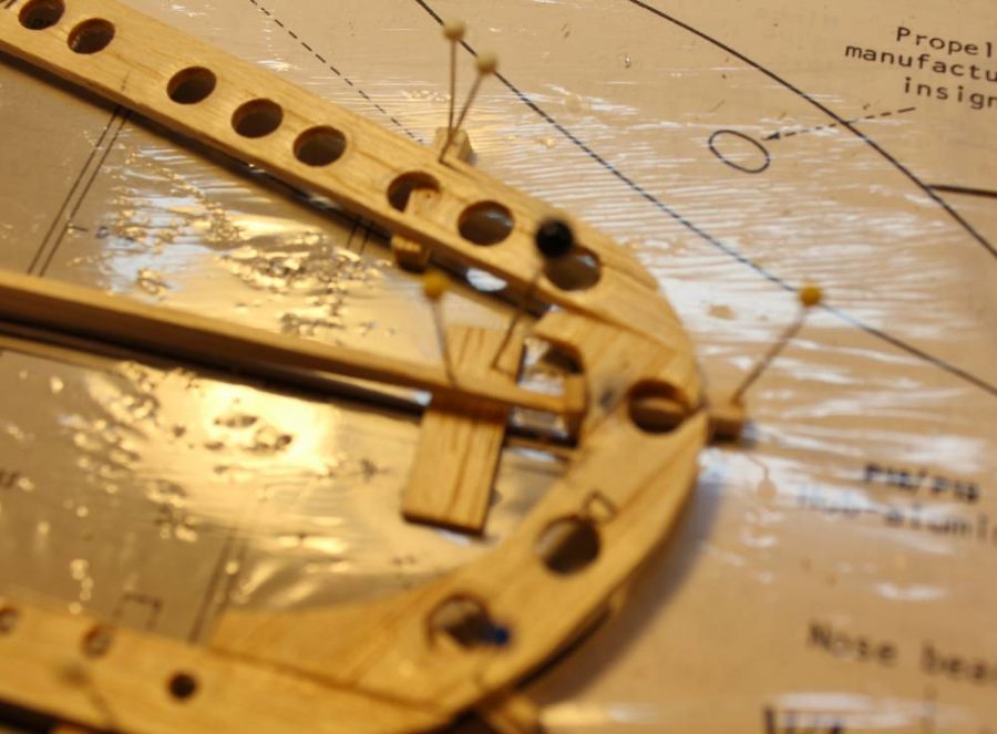
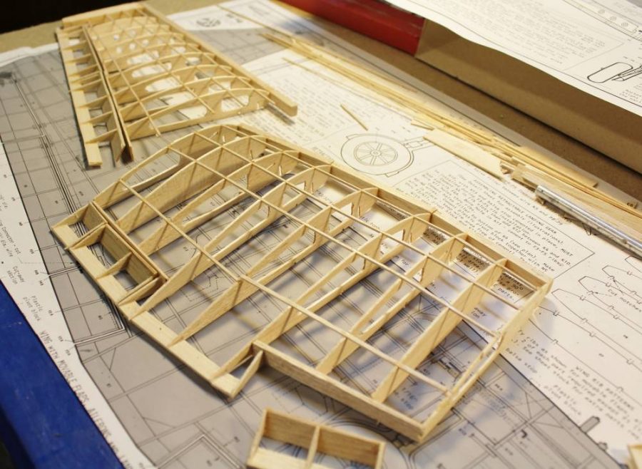
We are looking at the upper surface of the right horizontal tail tip. The 1/8” thick balsa spar is the beginning of Guillow’s “Action Plan” working control surfaces option that’s part of this kit.
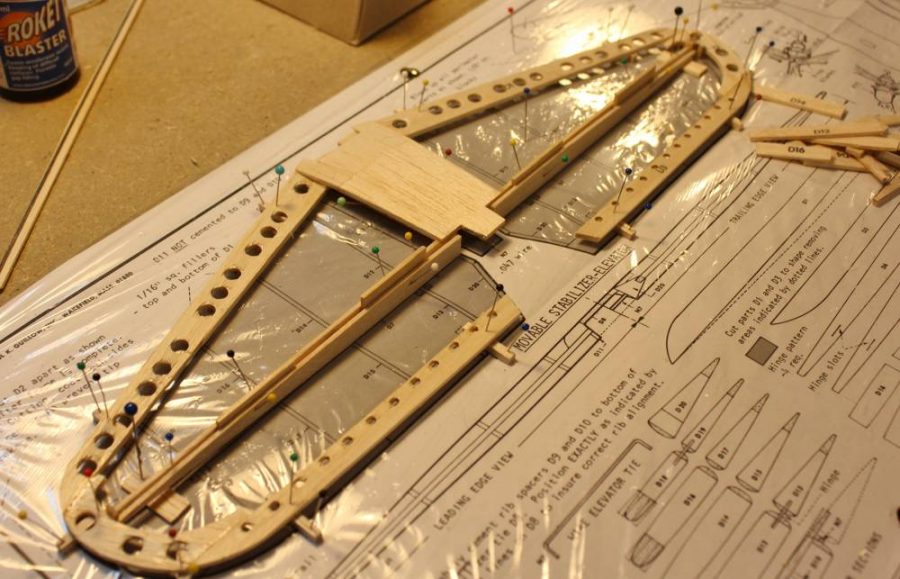
See how it goes together? Notice the temporary 1/16” sheet balsa spacers between the stabilizer trailing edge and the elevator leading edge? At this point everything is “stock Guillow’s kit” with the exception of the lightening holes.
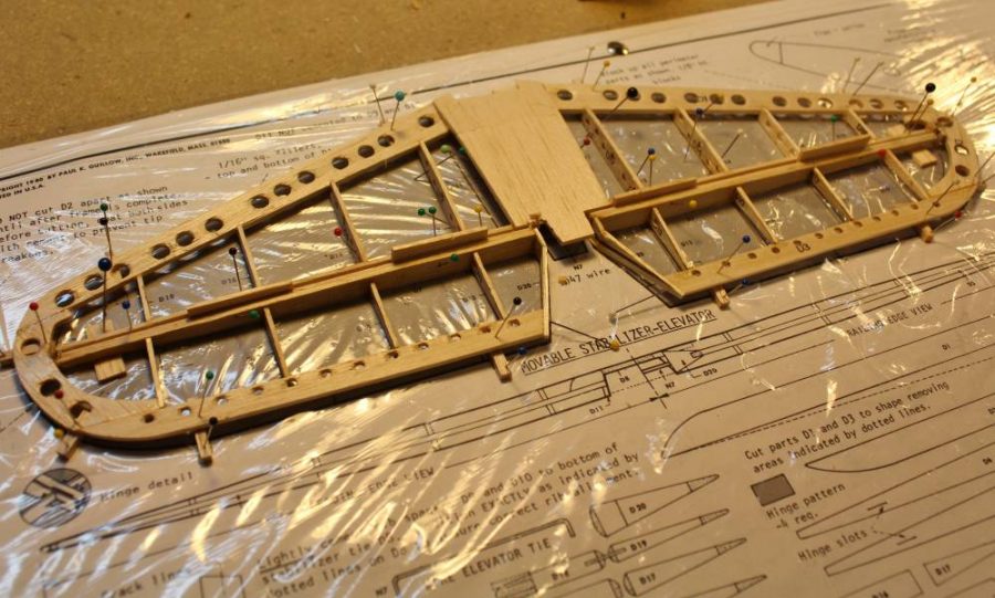
Here’s another look at the same structure with all the “ribs” in place. These are also standard die cut kit parts. Off-camera I have also built up the corresponding fin/rudder structure.
If you have read my stuff before you already know what’s coming next. SANDING is critical to doing a good job of building ANY balsa model airplane. What’s happening here is that I have placed a full sheet of 120-grit paper flat on my work surface so I can press-and-drag this elevator section across it for improved precision and control (and less chance of breaking it) that I could ever achieve using a loose-held sanding block (In real life, off-camera, I used my other hand to steady the sheet while moving the working part against it).
More of the same. Can you see how this method may very well be the only one you can use to sand a double taper into that trailing edge without destroying it?
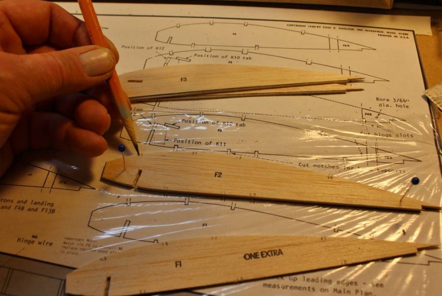
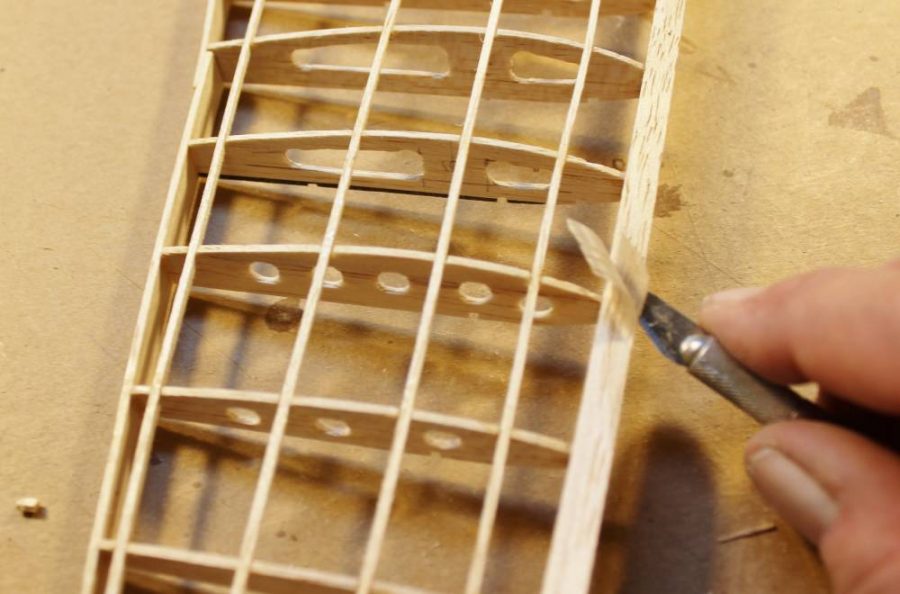
Back to working with those die cut parts. Exactly per the Guillow’s plan/instructions I made pencil marks along the edges of all the “F” parts (the wing ribs) to locate all the spar notch cutouts that need to be made. Guillow’s very wisely left theses delicate (1/16” sq.) cutouts to be marked and cut by hand in the interest of accuracy as well as to avoid lots of split balsa parts.
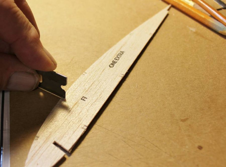
This is the best way I have found to make the initial cross-grain spar notch cuts and keep them all lined up.
I chose to clean up some of the spar notch cuts individually.
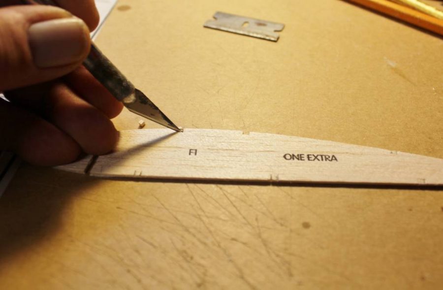
After that I used a No. 11 blade to finish cutting each notch along the grain. The razor blade is too wide to do that without making the cut oversize.
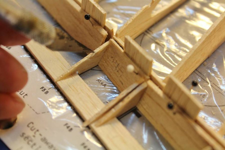
Our next job is to cut off all the wing rib trailing edges to form separate aileron and flap ribs. I’m making one big change here. The Guillow’s Action Plan shows parallel vertical cuts to create room for two 3/32” balsa sheet surface edges to fit into place parallel to each other. This anticipates “scale” control surfaces hinged at their mid-line, which would look OK for static display but won’t permit sufficient flap/aileron movement for real flying. Can you see how this change will allow then rear balsa piece (the flap/aileron leading edge) to be top-edge-hinged for a useful range of motion? NOTE: Both Guillow’s and I know that this approach does not replicate the true-scale Hellcat control surface cross sections and hinge geometry. I am making the judgment call that on a model this small the fussiness and extra weight of scale accuracy aren’t justified. What we’re doing here will look OK and work dependably.
I’m going to make some serious lightening holes in most of the wing ribs. For now I will make no cutouts in ribs F-3, F-4 and F-5. They become part of the modified landing gear installation which we will look at later, and at this point in the prototype construction I was not yet sure exactly what was going to be necessary. For now, mark the ribs you are going to lighten like this …
… then go ahead and define the corners of each opening with the same paper punch you used on the tail surface parts.
With all those corners punched it’s easy to finish cutting all the openings. The shape of the cutouts is not critical beyond taking care not to weaken any of the ribs by removing too much material …EXCEPT that the longer opening at the rear of all the inboard ribs will have to serve as pass-through openings for the aileron servo cables.
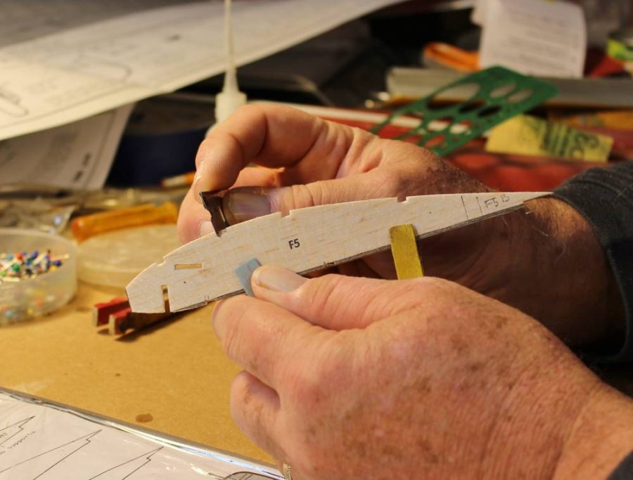
Before going on to assembling them it would be a good idea to bevel both ends of each rib like this so that they will fit precisely against the inner faces of the leading and trailing edges.
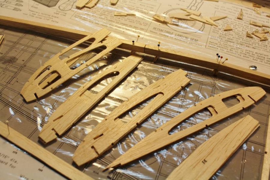
Ready for assembly the ribs look like this.
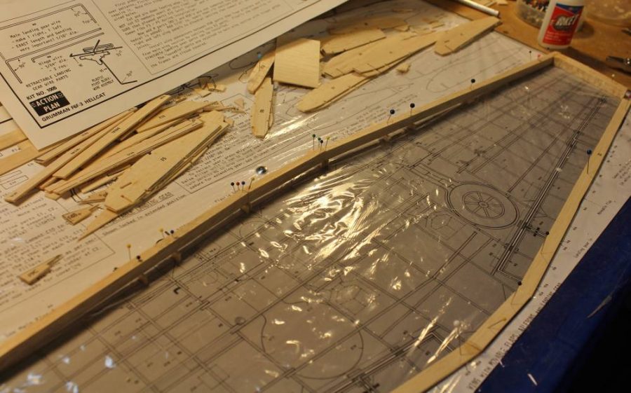
With all the wing ribs prepared for assembly the next step is to lay out all the leading and trailing edge parts (along with the wing tips) on the plan exactly per the Action Plan instructions.
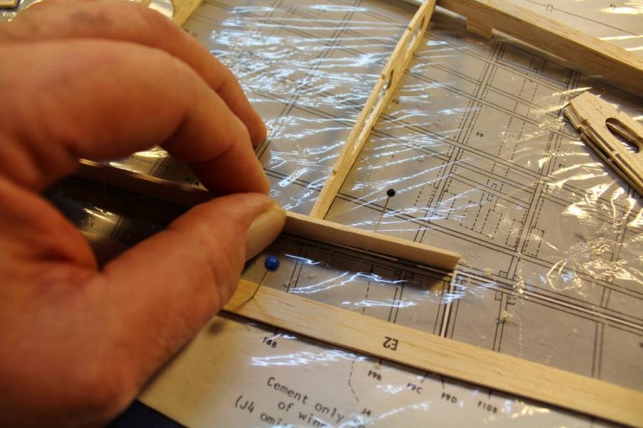
I have pinned this sub-trailing-edge (part M-2) in place so you can see how each rib in turn lines up with it.
Partially assembled the wing looks like this. We are building the center section and both outer panels flat on the building surface per the Guillow’s plans. At this point the only changes I have made in the wing are those lightening holes and the angled cuts for the control surface leading edges.
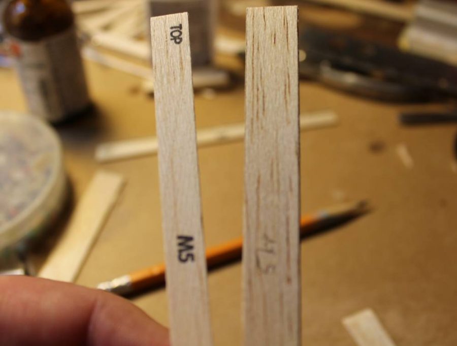
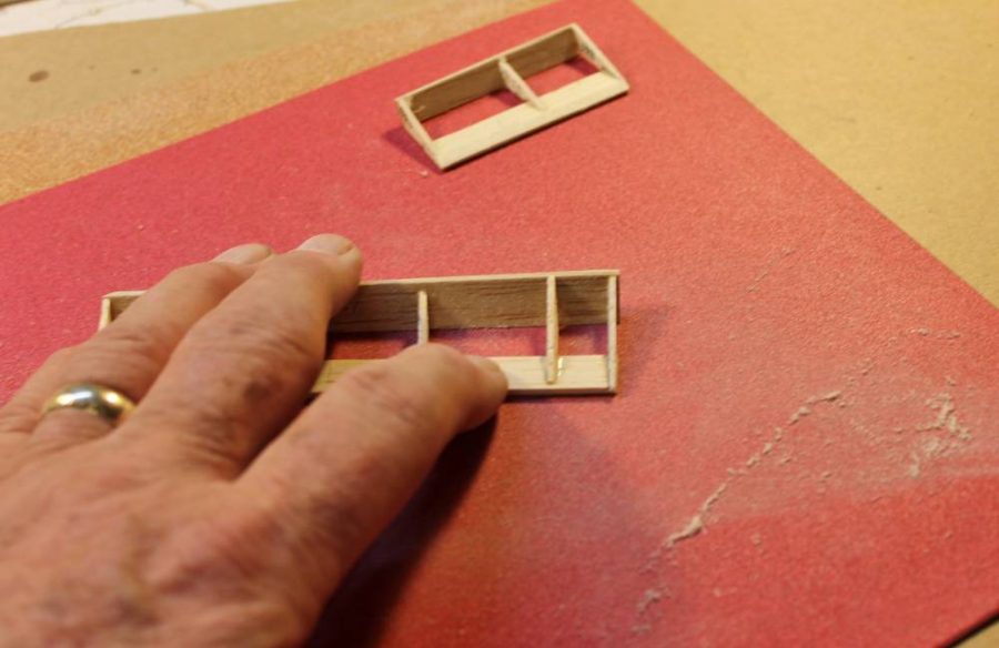
That changes now. As I mentioned in Step 17, I chose to modify the flap and aileron cross sections so they will operate properly as top-edge-hinged control surfaces. To make that work the flap/aileron leading edge parts (M-5 etc,) must be replaced with new parts that are wide enough to lie at a 45 degree angle to the wing trailing edge. You can use trigonometry to figure out this new width if you like, but I was OK with a cut-and-fit approach to making these changes. That’s the kit part on the left and the new one on the right.
This is a close-up look at part of the right wing flap assembly. The plans show you where each preliminary flap structure is cut apart to form three separate flaps sections on each wing. The 1/16” balsa sheet spacers are temporarily put in place per the Guillow’s kit instructions.
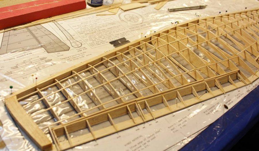
Here’s the entire primary wing structure in place on the work board. You can see the second change I made to the Guillow’s kit design if you examine the wing tip. In the kit this is a 3/32” sheet balsa “outline” part to which all the upper surface 1/16” sq. spars bend down and taper to blend in. Check out any full-scale reference photo or drawing (including the scale drawings on the plan) and you’ll see the discrepancy. I replaced the E-3 outlines by tracing them onto a piece of soft/light ½” thick balsa. Cut to the correct shape on my Dremel scroll saw they get assembled just as if they were the original parts. The 1/16” sq. spars that were to taper will now end flush against the inner face of each new tip block, which I will carve/sand to a finished contour after all the sheet balsa wing skin is in place.
Per the Guillow’s instructions I have cut the wing assembly apart to make separate center and outer panels as well as separate control surfaces.
This is the right outer panel. I am using a No. 11 blade to do some preliminary shaping of the leading edge. I’ll finish this job later with a sanding block.
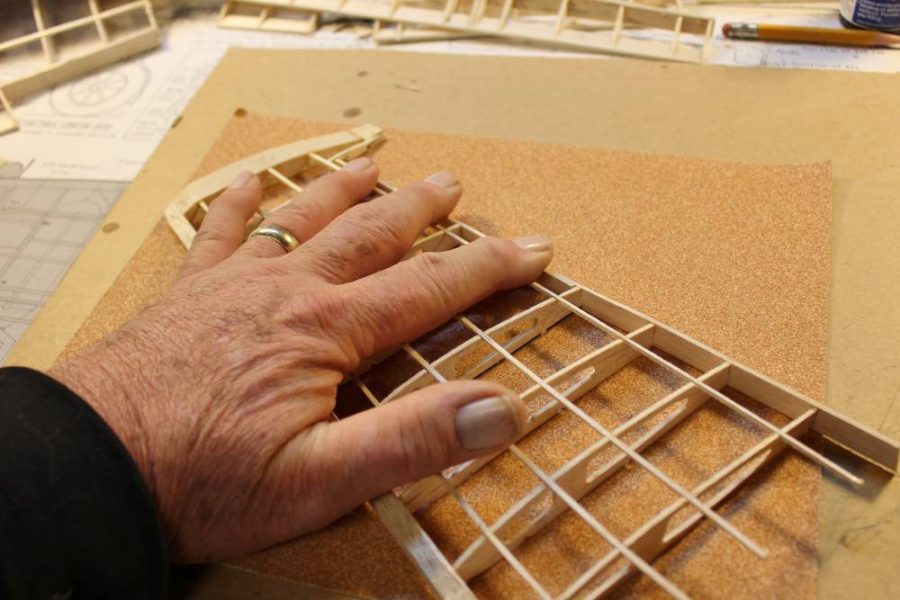
Do you remember the technique of sanding one entire surface of an assembled structure flat and true against a broad stationary abrasive sheet? One of the advantages of this method is the reduced risk of catching odd edges or corners and breaking the part.
Same deal goes for the flap sections …
… as well as for the bottom face of the center section.
This is one end of the underside of the center section. When you are finished that “make it all smooth and even” sanding job it should look like this.
Next time we’ll assemble the wing and work on the modifications I have planned for the landing gear.
LINKS
GUILLOW’S
DELUXE MATERIALS
The post Master’s Workshop #50: Guillow’s Hellcat RC Conversion appeared first on Fly RC Magazine.
Continue reading...
Wanna’ build a Hellcat? The box cover art Guillow’s has created for their entire line of balsa scale model airplane kits…all of which are Made in America … makes it hard to say no. Let’s talk about all those various kits for a moment. All Guillow’s kits on the market today are presented as stick-and-tissue “flying” models designed for rubber-powered free flight. Some of them, especially the few “non-scale” designs, can realistically be expected to fly that way. Most of the rest show a traditional rubber power prop setup on the plan and with the proper application of model building skill and patience they can be made to fly that way. Some of the more advanced/complex kits are advertised as “non-flying, display-only” models, but those still use the stick-and-tissue approach to design. In fact most of those display kits can be just as successfully converted to electric powered RC as can nearly all of the “flying” jobs. Some of these, like the 400 Series from which last month’s Spitfires come require lots of modification like figuring out working control surfaces as well as a custom RC installation. Others, like the 1000 Series which includes this Hellcat are larger and more complex and already include provision for working controls, which makes practical RC conversion easier. Our Hellcat is a good representation of this part of the Guillow’s line, which is why I have chosen it as our lead-off project. What we are going to do with it is to make those scale control surfaces work, add an appropriate electric motor, ESC and LiPo battery pack, and redesign/replace the original landing gear (with retracts in this case) with something that will survive real-world operations. In addition we are going to explore using several interesting alternative building techniques to improve the exterior surfaces in terms of both appearance and durability. Let’s get on with some model building and I’ll explain each of these modifications as we go along.
Let’s begin by getting down to the real basics … what to with all those balsa parts. Some of the “conversion-friendly” kits (like those Kit No. 403 Spitfires) have been upgraded to laser cutting. The Hellcat is not one of these…it depends on the time-honored (and less than perfect) process of die cutting. We have already talked a lot about this. Right now I’m showing you one of the best ways to deal with die-cut parts sheets that may be rough, slightly heavier than you’d like, and not fully cut-through. We are going to sand down the back of each sheet to get a smoother surface, get rid of any excess thickness/weight we don’t really need, and free up any and all incomplete cuts from the back side, which is where the dies may have failed to reach. How much of this you may need to do will vary from one kit to the next. With this Hellcat I chose to use a 220-grit sander to take off about 1/64” of balsa.
This is the result. The surface of the balsa is really smooth, and most important, the shallow die cuts have been corrected so the various parts are nearly ready to fall out on their own.
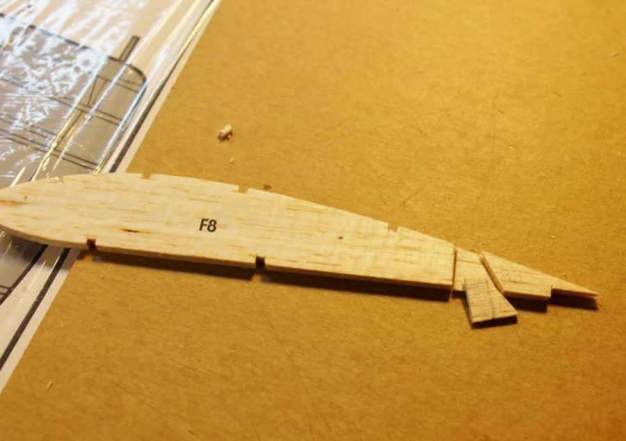
Die-cut balsa parts, unlike their laser-cut cousins, are by definition going to be less consistently accurate. This is true for just about any die-cut kit, not just Guillow’s. This is one of the horizontal tail outline parts as it came out of the sheet … can you see the rough edge?
You could assemble it as-is, but you shouldn’t. That roughness equates to extra weight, poor parts fit and degraded glue joint strength as a result of the loose joint caused by that roughness. The 320-grit sanding block is the fix for all of that.
See the nice smooth, crisp edge that results from a minute or so of extra care? This is one of those old-timer model building “secrets” that you have to want to learn about to do this stuff right.
I’m not sure whether this is “old time” or not…I have never seen anyone else do this. An ordinary ¼” paper punch will make clean holes through soft to medium balsa sheet up to about 3/32” thick. Removing weight from the tail of any model is a good idea if you can do it without compromising structural integrity. These edge parts are going to get some serious reinforcement before long that will work in concert with the lightening holes…watch for what I’m going to do.
We are looking at the upper surface of the right horizontal tail tip. The 1/8” thick balsa spar is the beginning of Guillow’s “Action Plan” working control surfaces option that’s part of this kit.
See how it goes together? Notice the temporary 1/16” sheet balsa spacers between the stabilizer trailing edge and the elevator leading edge? At this point everything is “stock Guillow’s kit” with the exception of the lightening holes.
Here’s another look at the same structure with all the “ribs” in place. These are also standard die cut kit parts. Off-camera I have also built up the corresponding fin/rudder structure.
If you have read my stuff before you already know what’s coming next. SANDING is critical to doing a good job of building ANY balsa model airplane. What’s happening here is that I have placed a full sheet of 120-grit paper flat on my work surface so I can press-and-drag this elevator section across it for improved precision and control (and less chance of breaking it) that I could ever achieve using a loose-held sanding block (In real life, off-camera, I used my other hand to steady the sheet while moving the working part against it).
More of the same. Can you see how this method may very well be the only one you can use to sand a double taper into that trailing edge without destroying it?
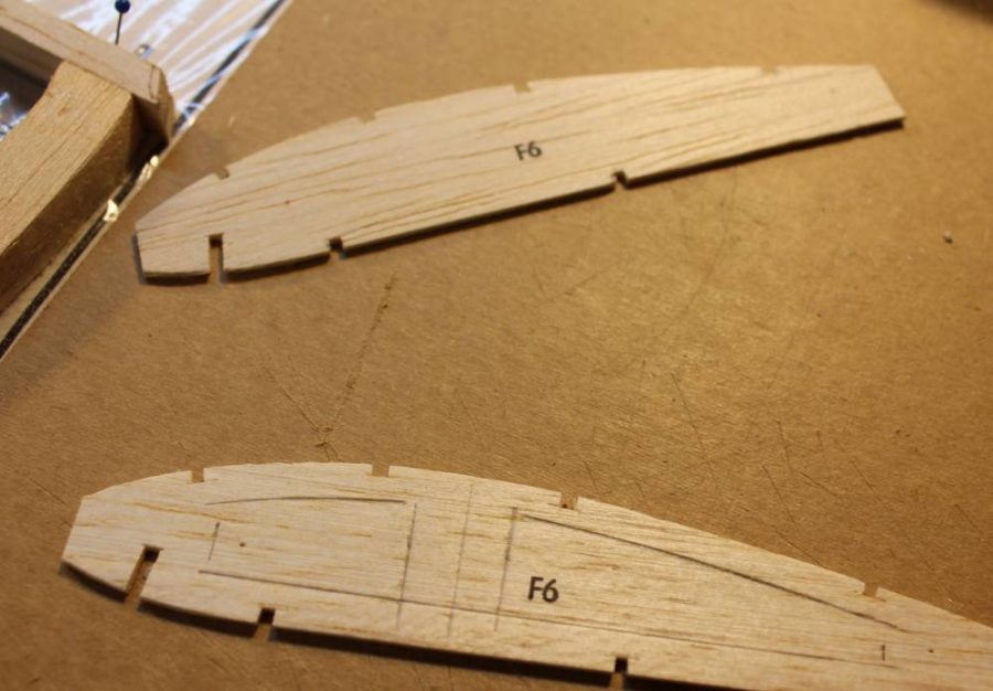
Back to working with those die cut parts. Exactly per the Guillow’s plan/instructions I made pencil marks along the edges of all the “F” parts (the wing ribs) to locate all the spar notch cutouts that need to be made. Guillow’s very wisely left theses delicate (1/16” sq.) cutouts to be marked and cut by hand in the interest of accuracy as well as to avoid lots of split balsa parts.
This is the best way I have found to make the initial cross-grain spar notch cuts and keep them all lined up.
I chose to clean up some of the spar notch cuts individually.
After that I used a No. 11 blade to finish cutting each notch along the grain. The razor blade is too wide to do that without making the cut oversize.
Our next job is to cut off all the wing rib trailing edges to form separate aileron and flap ribs. I’m making one big change here. The Guillow’s Action Plan shows parallel vertical cuts to create room for two 3/32” balsa sheet surface edges to fit into place parallel to each other. This anticipates “scale” control surfaces hinged at their mid-line, which would look OK for static display but won’t permit sufficient flap/aileron movement for real flying. Can you see how this change will allow then rear balsa piece (the flap/aileron leading edge) to be top-edge-hinged for a useful range of motion? NOTE: Both Guillow’s and I know that this approach does not replicate the true-scale Hellcat control surface cross sections and hinge geometry. I am making the judgment call that on a model this small the fussiness and extra weight of scale accuracy aren’t justified. What we’re doing here will look OK and work dependably.
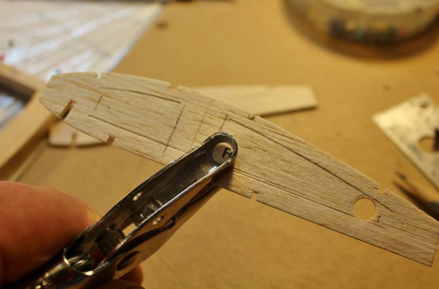
I’m going to make some serious lightening holes in most of the wing ribs. For now I will make no cutouts in ribs F-3, F-4 and F-5. They become part of the modified landing gear installation which we will look at later, and at this point in the prototype construction I was not yet sure exactly what was going to be necessary. For now, mark the ribs you are going to lighten like this …
… then go ahead and define the corners of each opening with the same paper punch you used on the tail surface parts.
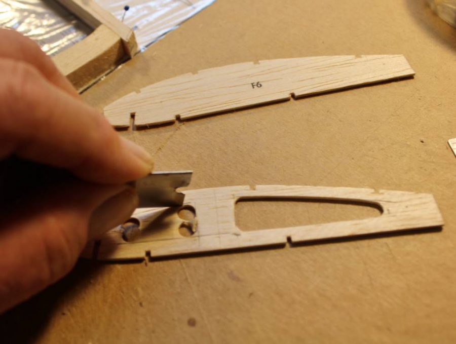
With all those corners punched it’s easy to finish cutting all the openings. The shape of the cutouts is not critical beyond taking care not to weaken any of the ribs by removing too much material …EXCEPT that the longer opening at the rear of all the inboard ribs will have to serve as pass-through openings for the aileron servo cables.
Before going on to assembling them it would be a good idea to bevel both ends of each rib like this so that they will fit precisely against the inner faces of the leading and trailing edges.
Ready for assembly the ribs look like this.
With all the wing ribs prepared for assembly the next step is to lay out all the leading and trailing edge parts (along with the wing tips) on the plan exactly per the Action Plan instructions.
I have pinned this sub-trailing-edge (part M-2) in place so you can see how each rib in turn lines up with it.
Partially assembled the wing looks like this. We are building the center section and both outer panels flat on the building surface per the Guillow’s plans. At this point the only changes I have made in the wing are those lightening holes and the angled cuts for the control surface leading edges.
That changes now. As I mentioned in Step 17, I chose to modify the flap and aileron cross sections so they will operate properly as top-edge-hinged control surfaces. To make that work the flap/aileron leading edge parts (M-5 etc,) must be replaced with new parts that are wide enough to lie at a 45 degree angle to the wing trailing edge. You can use trigonometry to figure out this new width if you like, but I was OK with a cut-and-fit approach to making these changes. That’s the kit part on the left and the new one on the right.
This is a close-up look at part of the right wing flap assembly. The plans show you where each preliminary flap structure is cut apart to form three separate flaps sections on each wing. The 1/16” balsa sheet spacers are temporarily put in place per the Guillow’s kit instructions.
Here’s the entire primary wing structure in place on the work board. You can see the second change I made to the Guillow’s kit design if you examine the wing tip. In the kit this is a 3/32” sheet balsa “outline” part to which all the upper surface 1/16” sq. spars bend down and taper to blend in. Check out any full-scale reference photo or drawing (including the scale drawings on the plan) and you’ll see the discrepancy. I replaced the E-3 outlines by tracing them onto a piece of soft/light ½” thick balsa. Cut to the correct shape on my Dremel scroll saw they get assembled just as if they were the original parts. The 1/16” sq. spars that were to taper will now end flush against the inner face of each new tip block, which I will carve/sand to a finished contour after all the sheet balsa wing skin is in place.
Per the Guillow’s instructions I have cut the wing assembly apart to make separate center and outer panels as well as separate control surfaces.
This is the right outer panel. I am using a No. 11 blade to do some preliminary shaping of the leading edge. I’ll finish this job later with a sanding block.
Do you remember the technique of sanding one entire surface of an assembled structure flat and true against a broad stationary abrasive sheet? One of the advantages of this method is the reduced risk of catching odd edges or corners and breaking the part.
Same deal goes for the flap sections …
… as well as for the bottom face of the center section.
This is one end of the underside of the center section. When you are finished that “make it all smooth and even” sanding job it should look like this.
Next time we’ll assemble the wing and work on the modifications I have planned for the landing gear.
LINKS
GUILLOW’S
DELUXE MATERIALS
The post Master’s Workshop #50: Guillow’s Hellcat RC Conversion appeared first on Fly RC Magazine.
Continue reading...