GSNadmin
Staff member
By Bob Benjamin – bob@rcmodel.com
Last month we ran out of page space with all panels of the wing framed up, ready to be joined at the correct dihedral angles to prepare for a sheet balsa covering job that might be a little different from what you are used to. We finished off with a view of the bottom surface of the center section to serve as an example of the way all ribs, edges, etc. have got to blend together without any bumps or discontinuities that would spoil the final surface. Sanding is the magic technique to make that happen, so we will start off this session with more of that.
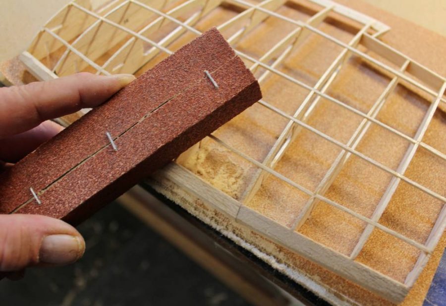
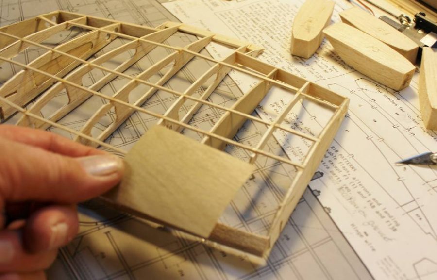
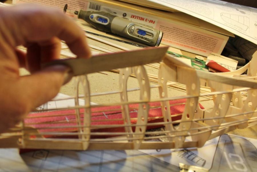
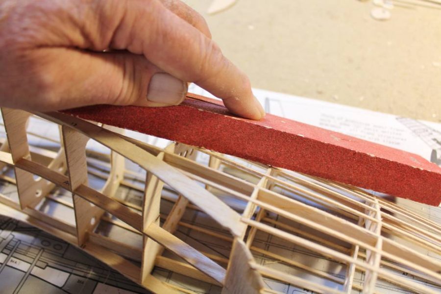
This is the surface of the wing center section, which has been assembled so far exactly per the Action Plan layout. Note that the bottom/lower 1/16” sq. balsa spars aren’t in place yet. Earlier you saw me doing some rough shaping of the stock kit leading edge with a No. 11 blade; here I’m using my 80-grit sanding block to finish the top surface of the leading edge so that it becomes a flat surface extending ahead of the ribs. The plans suggest that you need to round off the front of the LE. Don’t do that…leave a flat surface like this and on the bottom as well.
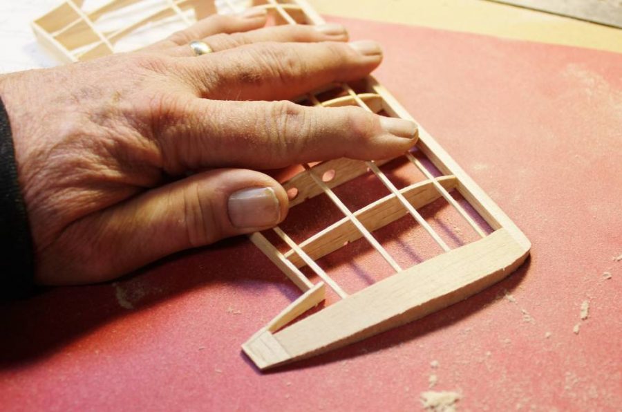
You have seen me doing this before. This is the right outer wing panel including the partially shaped modified balsa block tip getting sanded to the same level of accuracy we saw last time on the bottom of the center section.
Now we are going to make some serious modifications to permit mounting a set of E-Flite 10-15 90 degree rotating retracts. I have already established to my satisfaction that a slightly smaller Guillow’s fighter (the Kit. No. 403 Spitfire) will fly well with the ordinary side-rotating E-Flite retracts, so we know this is going to work. Note: I have checked out many mechanical, pneumatic and electric mini-retracts. What I’m sharing with you here is the smallest, lightest RLG installation that I feel I can trust for real-world flying. If you are aware of a commercially available system that you believe might work better, please let us know about it.
Back to wing modification. I made 1/64” aircraft plywood doublers for F-3 and F-5 that fit on each inside face of the respective ribs to serve as hard mounting surfaces for the RLG mounting blocks I’ll show you next. ALSO NOTE: If you include this modification on your Guillow’s Hellcat you will discover that there’s a lot of cut-and-fit work involved. The important measurements to get right are the position of the upper retract pivot point, the forward rake built into those mounting blocks, and the length of the strut. Make all this stuff match the Guillow’s Action Plan as closely as you can.
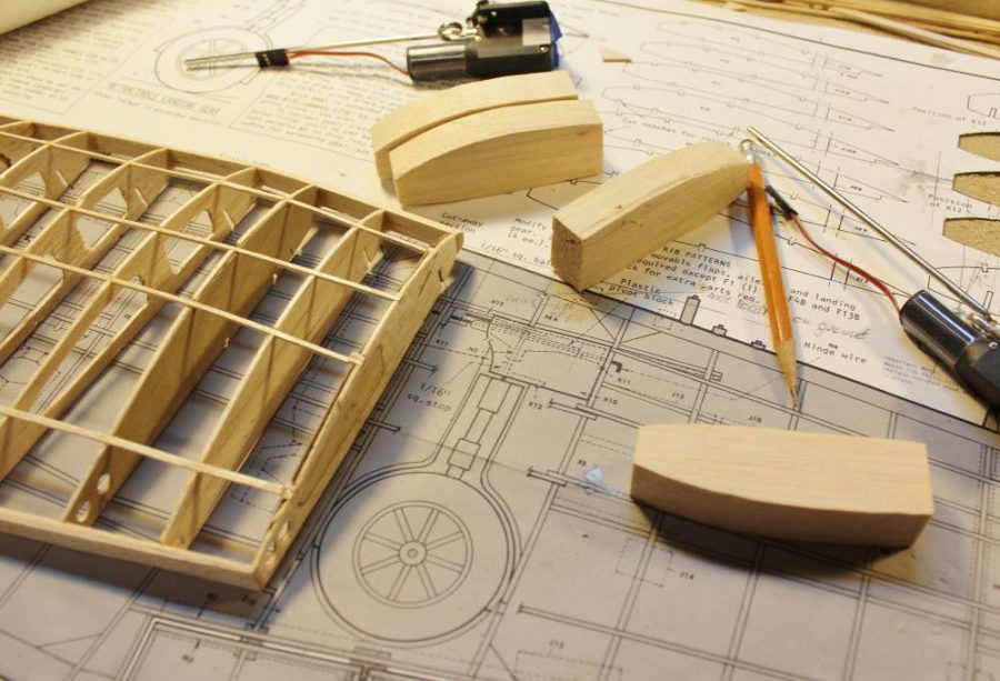
There are four RLG mounting blocks that I cut and shaped from medium-weight balsa block. You may be able to see some of my changes marked on the plan in pencil as well. Watch how this comes together and it will all make sense.
This modification puts the inside/upper portion of the retract units so close to the inner face of the top wing skin that I chose to add some extra reinforcement to the front of the landing gear bay. I cut this 1/64” plywood doubler plate to fit flush with the top/outer edges of ribs F-3 and F-5. If you study the image you’ll see how it’s going to fit into place. NOTE: By the time we have removed enough balsa for the mounting blocks and RLG units to fit there’s not much left of rib F-4.I left that rear upper edge in place to help locate the sheet balsa wing skin that’s coming later.
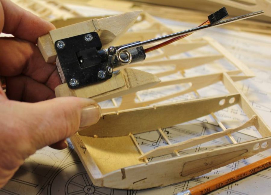
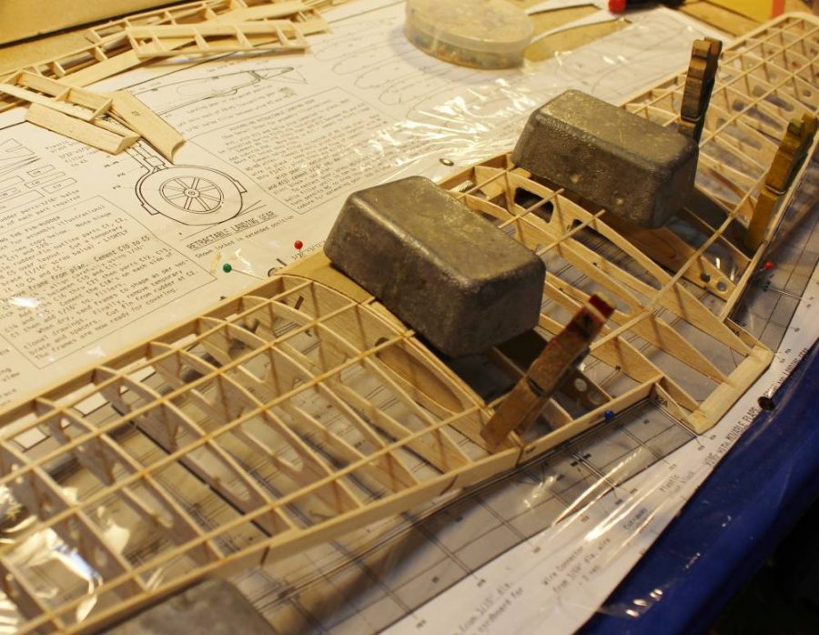
Having measured and marked all the dimensions and clearances carefully, I located the mounting screw holes in each of the blocks with them outside the airplane. The reason for this is to ensure that each RLG unit fits square and true against what will become its mounting base plate. You can trim the outer dimensions of the assembled RLG/block units as needed to fit the wing structure correctly. If you install the blocks first you risk having them line up with the RLG units incorrectly, which will cause stress and possible failure.
See how it all comes together? We’ll worry about those over-length struts later.
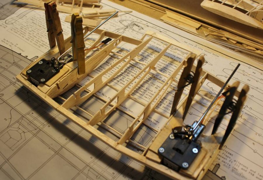
Same game from above. If you study this assembly carefully you can work out how I’ve attempted to distribute the landing loads over as much of the original, pre-modification wing structure as possible.
My next step was to remove the RLG units, assemble the various wing sections in place on the Guillow’s Action Plan, and join them per the kit instructions.
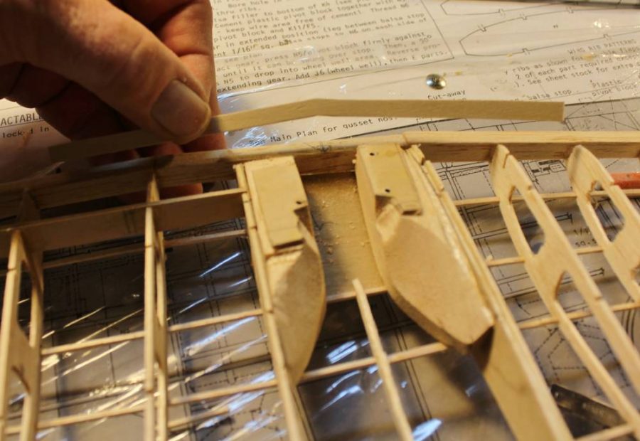
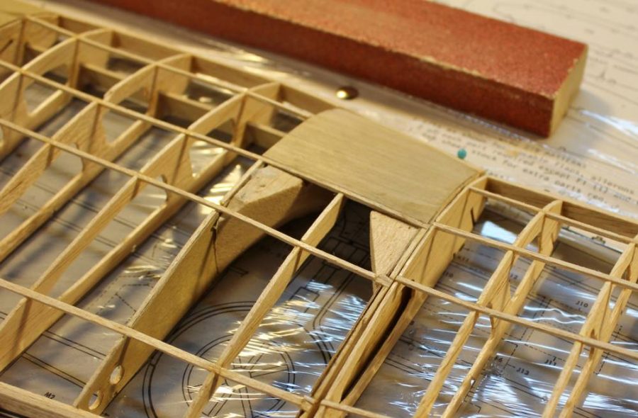
With all the material I removed from the original structural design it was necessary to replace some of the strength that went with it. I made a pair of new leading edge doublers from 1/32” plywood, cut appropriate clearance slots between the front of each affected rib and the inside face of the leading edge and assembled it all with Plenty of Deluxe Materials Aliphatic Resin glue. NOTE: After shooting this image I secured each spar/leading edge assembly with some of those modified heavy duty clothespin clamps you have seen before.
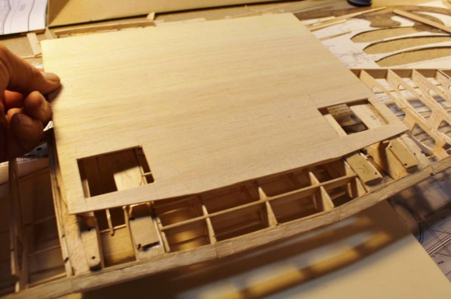
I decided to fully cover/enclose the wing center section with 1/16” sheet balsa before putting the entire wing assembly aside to work on the fuselage. This is the bottom surface sheet cut as nearly to exact shape as I can get it before assembly. I’m going to use an unusual technique to attach the sheet balsa covering, which I’ll describe a bit later.
With the wing structure set aside for a while I’m going to start work on the fuselage to get it caught up with the rest of the airplane. All the fuselage center keel parts (A-1 through A-5) are assembled exactly per the Guillow’s Main Plan. In addition to that first step I have glued fuselage former B-1 in place perpendicular to the assembled keel parts. Unlike the pair of laser-cut Kit. No. 403 Spitfires I told you about in my lead article on Guillow’s kits, this Hellcat along with the other four 1000 Series kits is still a die-cut product. Like most of Guillow’s other scale model designs, this one uses a fuselage structure based on a vertical center keel which is assembled from several die-cut parts and then “filled out” with a series of balsa half-formers that define the left half of the structure. What’s happening here is that I have assembled the keel in place over the fuselage layout on the Main Plan and added the left side of half-former B-1.
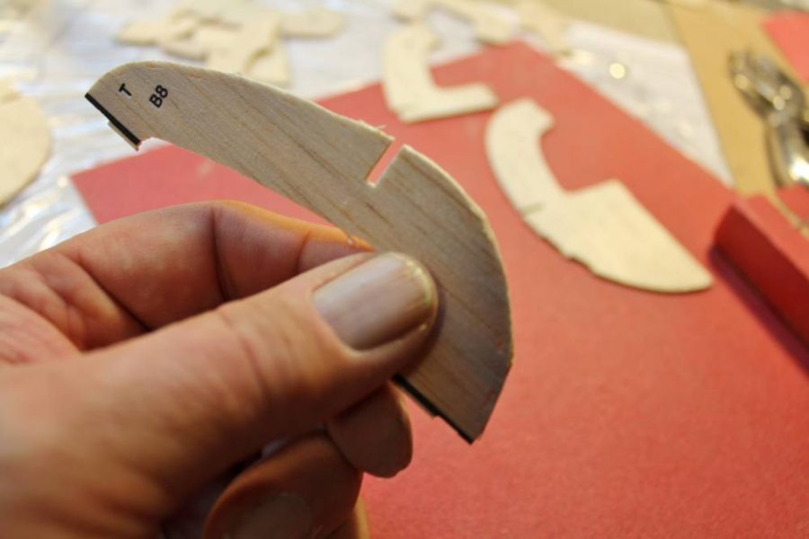
Before we go any further let’s take a closer look at a representative die-cut fuselage former. This is B-8 (the first former behind the wing trailing edge). Remember that we have already explained Guillow’s willingness to replace any die-cut parts sheets of questionable quality? This 1/16” sheet part is cut from balsa that’s OK for this application, but there are some things we can do to improve it. Can you see the slightly uneven, soft-looking cut on the corner of the former away from my thumb?
Sanding is the cure for this little piece of balsa’s shortcomings. First I flat-sanded each face of the part down to 220-grit smoothness while removing about 1/64” of thickness and weight…
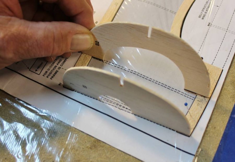
…and then off-camera I turned the former on-edge and used that same sanding block to clean up any sloppy edges I could find. Here you can see half-formers B-1 and B-2 finish sanded and glued in place on the keel.
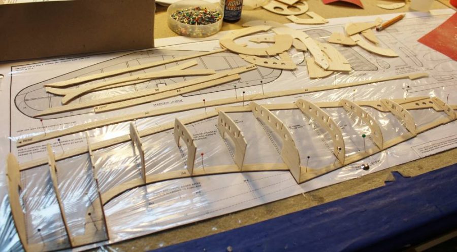
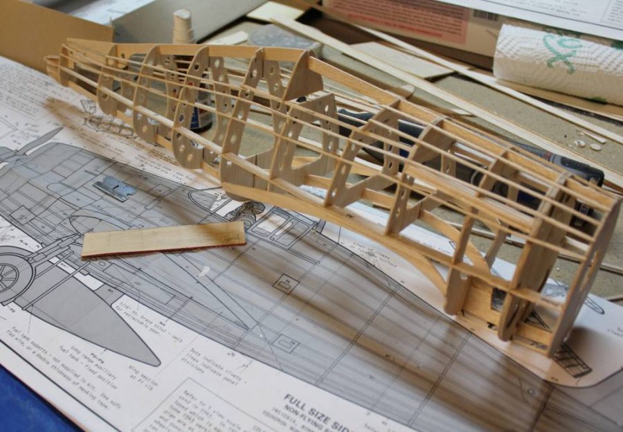
The next several steps in fuselage assembly go exactly per the Guillow’s kit instructions. Here you can see half-formers B-1 through B-11 assembled in place to define the left half of the fuselage. The “extra” parts at the rear are for the right side half-formers and fuselage side keels.
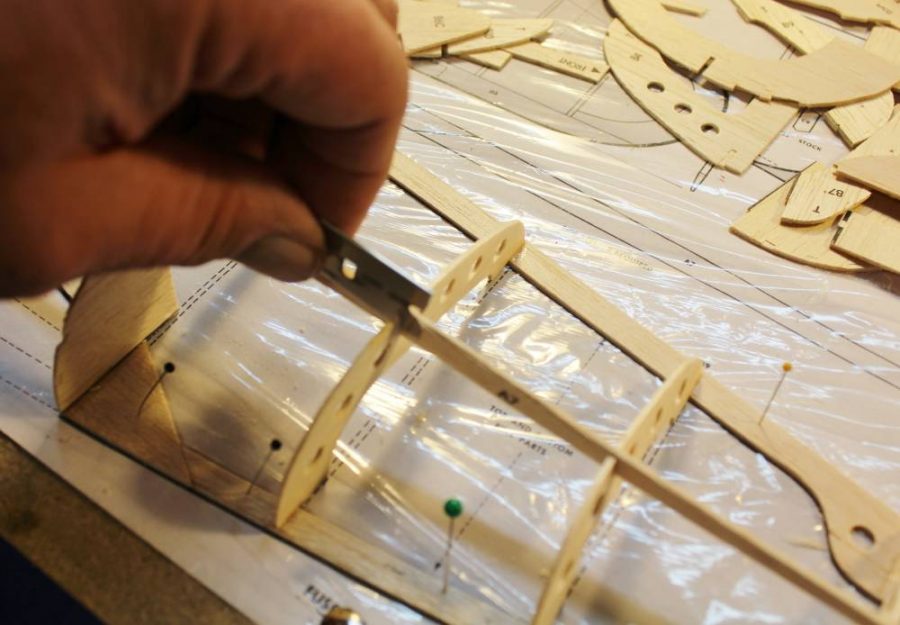
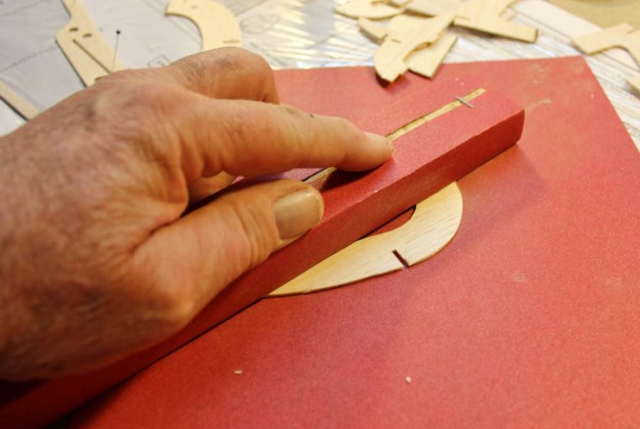
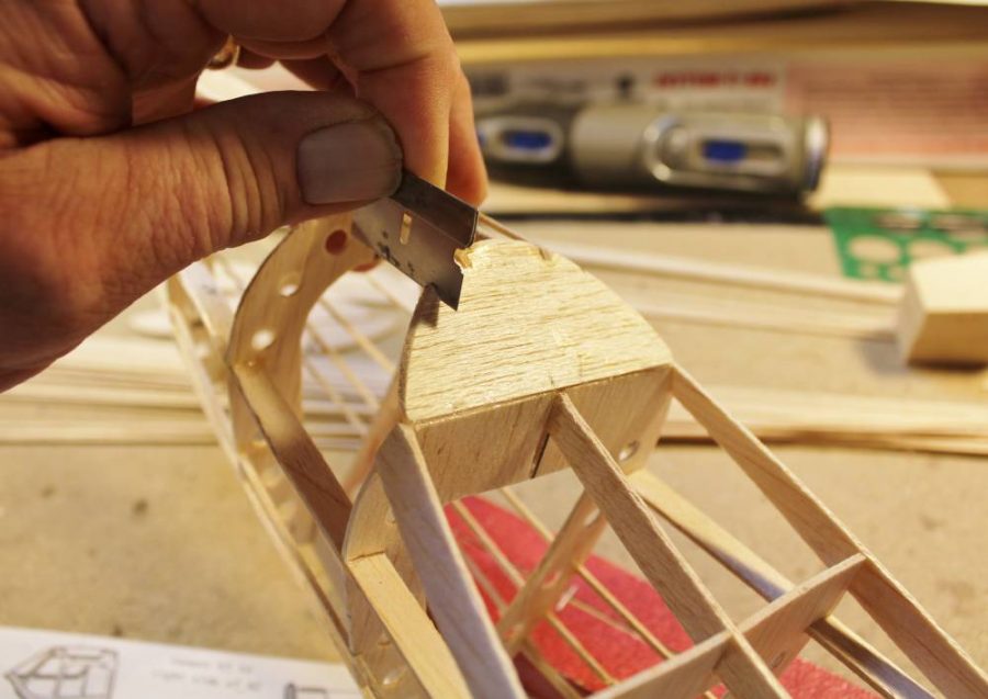
The next step, again following the Guillow’s Main Plan and instruction/assembly guide, is to glue the two left side-keel pieces (A-5 and A-6) into a single unit and then slip them into place in all the formers. Notice here that I am using a single-edge razor blade to trim the side keel notch in B-8 for an exact fit. When building a die-cut kit such as this one you have to be ready to adjust any of the pre-cut slots. In this case the notch centered about 3/64” too low with the result that the side keel had to bow out of line to fit into it. It’s up to you as a responsible model builder to make these simple corrections whenever you find the need for them.
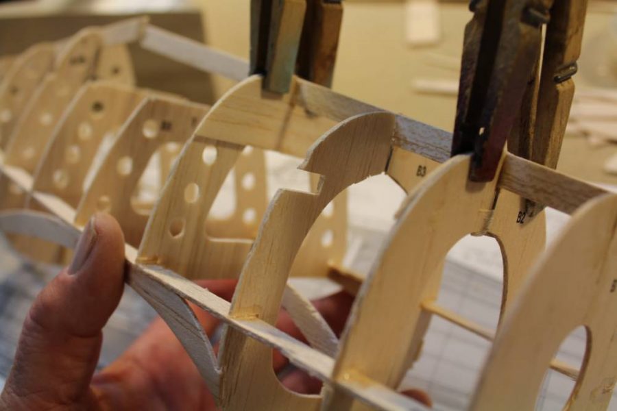
Fully assembled in place the corresponding right side keel looks like this. If you look carefully you’ll see that I have traced and cut out doublers for the top portions of B-2 and B-4. This is a departure from the Guillow’s plan that becomes the first step in creating a removable battery pack access hatch. Can you see the squared-off cutout in B-3 that aligns with the bottom of those new doubler formers?
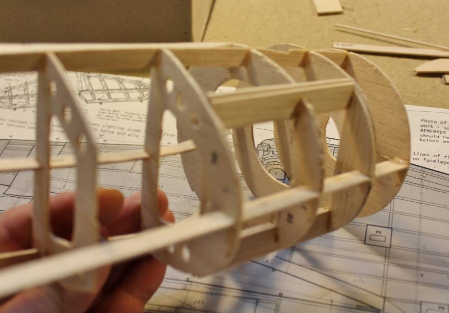
The next step in modifying the standard fuselage for that hatch is to install two inset 3/32” balsa sheet rails as you see here on both sides of the fuselage. These rails, which become edges/liners for the hatch and cutout, are glued to everything around them, but NOT to each other.
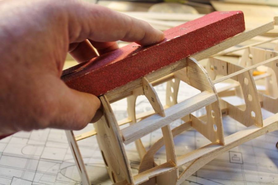
Now I’m using a 120-grit sanding block to trim the outer faces of those assembled hatch rails flush with the outside edges of all the surrounding formers.
The next step, this time right in line with the standard kit assembly sequence, is to install all the 1/16” sq. balsa fuselage stringers. Here again is a situation that will very probably require you to do some trimming of the die-cut stringer notches to ensure that all the stringers line up on-center, straight, and evenly spaced from their neighbors. If there’s any doubt dry-fit a stringer in place and sight along it end-on. Any waves or wiggles you can see have to be corrected by trimming those holes. Here I’m using a custom tool that I made for this job. The piece of wood in my hand is a length of 1/16” plywood with a carefully-cut 1/16” wide strip of 120-grit sandpaper glued along each of the long edges. Aligned with what should be the exact location of a series of stringer notches, moving it back and forth in a sawing motion will leave neatly-cut notches just where the plans say they should be.
Here’s another look at the same process with several top stringers located and glued into place. NOTE: Follow the instructions that come with then kit and always install stringers IN PAIRS…right, left, right, left etc. At this point in its assembly a fuselage structure like this one is pretty floppy and at risk of being permanently twisted if you don’t keep the stringers from adding unbalanced stresses as you install them.
Here’s another significant modification from the original plan. As designed, former B-7 is flat/straight from top to bottom. If the model is built that way, with the wing permanently joined to the fuselage, this doesn’t matter. BUT, with a removable wing such as we are going to use there are two new issues to deal with. First, with the leading and trailing edge formers (in this case B-3 and B-7) are left flat, the process of inserting/assembling the wing into the finished fuselage will be a fussy job of keeping everything perfectly in alignment AND you won’t be able to use a dowel stub at either the leading or trailing edge per usual RC practice because there won’t be any way to rotate the wing into place to insert it. Second, if the model ever hits something you didn’t want it to…OK, we won’t use the “C” word…the beveled/angled rear face of the wing cutout that’s created by angling the bottom of B-7 will give it room to “knock off” without taking a lot of the rear fuselage with it. Also, did you notice that here I’m using a razor blade to cut stringer notches that line up with the rest of the formers?
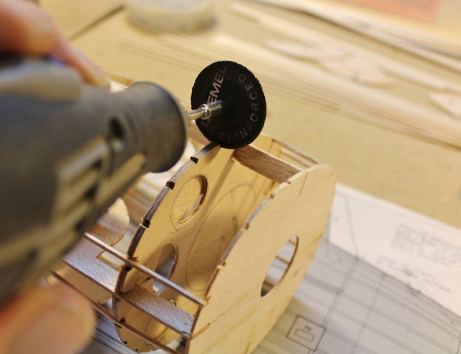
Once again while you weren’t looking I added an extra part…in this case a duplicate former B-2 cut from 1/16” aircraft plywood. This is going to take over the function of the plywood former/firewall that was originally designed to attach to the front of B-1. In recent Guillow’s kits several 1/16” plywood parts have been replaced by a die-cut sheet of white vinyl material. I cannot recommend that you use any of this stuff. Not only is it less dimensionally stable than the plywood it’s supposed to replace, it’s three to four times heavier than an equivalent plywood part. With all that said, the new B-2 doubler plywood firewall must have all those stringer notches cut into it to match B-2, This is not a job for a lone unsupported razor blade. If you can measure out and mark the notch positions you can pre-cut them on a scrollsaw before assembly OR you can use the edge of a Dremel grinding disc like this to do the slotting in place.
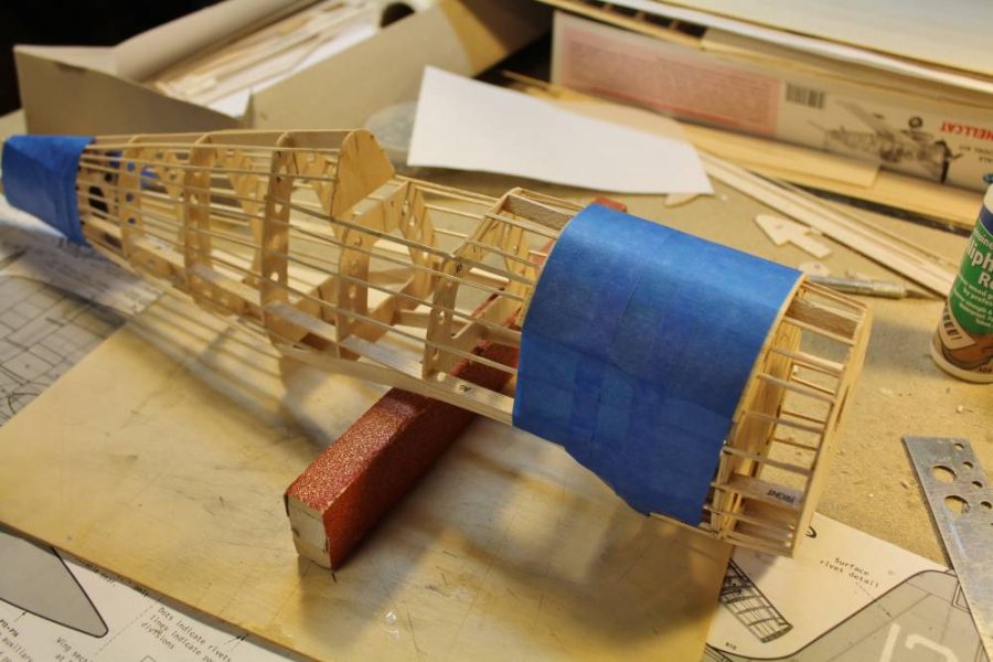
With all the formers and 1/16” sq. balsa fuselage stringers in place it’s time for some serious sanding. We are going to create a very closely-fitted sheet balsa skin over this surface, and any bumps or other errors WILL show through. Another note…if we were planning to retain the open structure…tissue covering over open stringers…I would “scallop” the formers between each pair of stringers to avoid that poked-through “starved horse” look that results from leaving those rounded-off outer edges to protrude. But, since we’re going to use balsa sheet covering which creates and maintains its own curvature, we are going to leave the formers as designed to help that balsa sheet assume the curved “round” shape we want for this airplane.
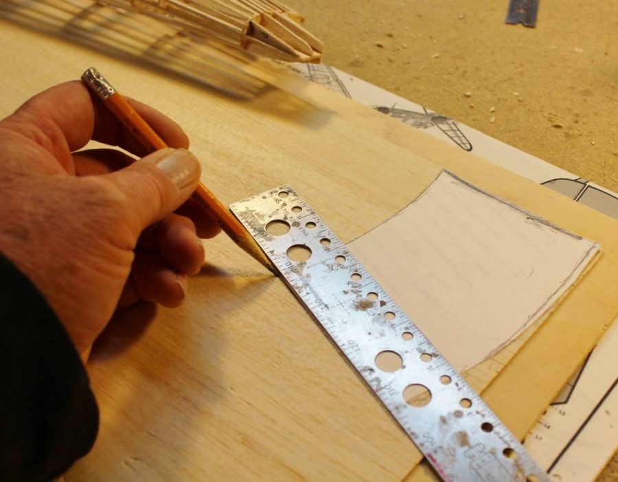
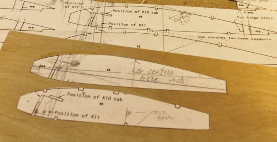
The next step in this process is to measure and cut out the actual sheet balsa panels that are going to become part of the fuselage. I’m going to use the best quality light 1/16” balsa sheet I can find. This not something Guillow’s currently includes in their kits. Why 1/16” and not something lighter like 1/32”? In a word, SANDING. Balsa sheet slightly thicker than we want the finished fuselage skin to be is the answer. The extra thickness provides material to “sand on”, to blend less-than-perfect panel edge joints along with any other errors that are going to appear in a job like this no matter how carefully we work. What you see here is one of the ordinary bond paper patterns I made to fit specific sections of the fuselage. The criterion here is that the dimensions/size of each panel must allow it to be attached creating only single-curvature bends.
Like here. What you see here is two separate 1/16” balsa sheet skins that meet/join along the bottom fuselage keel. I wet each piece thoroughly with plain water and then attach it with Deluxe Materials Aliphatic Resin glue, which is water-based. You’ll get a closer look at how I do this in a bit. Masking tape is the best way I have found to keep sheet skin like this in place while everything dries without damaging it the way pins would.
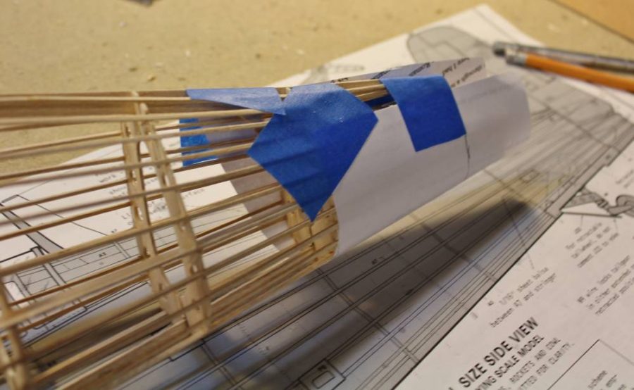
I can’t work on the adjacent tail panels with all that tape still in place so I went to the front instead to attach more of that 1/16” balsa sheet skin over then portion of the nose that’s going to become the removable battery hatch. Here it’s easy to see how that masking tape holds the wet balsa sheet and still-wet glue precisely in place.
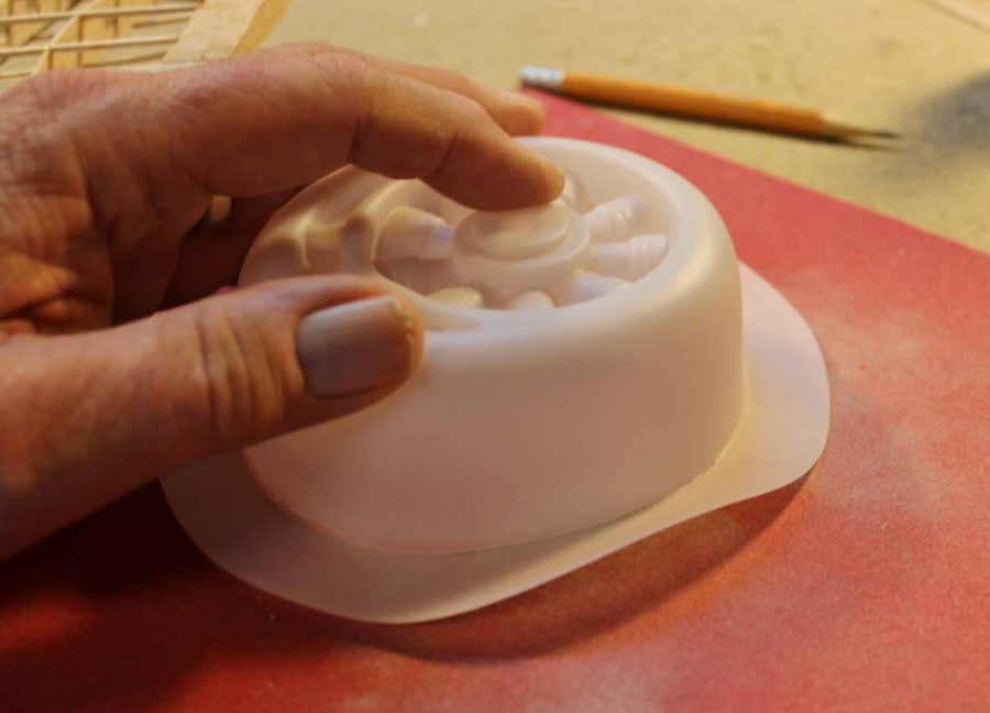
While I was waiting for these two “wet balsa” layups to dry I decided to work on the cowl. This is going to turn out to be very different from the original Action Plan design, but I’m going to base it all on the standard Guillow’s molded plastic cowl. You can pretty well see “just looking” how I prefer to trim parts like this from their matrix sheets. I doubt that I could come as close to the accuracy I’m getting here using scissors or a blade.
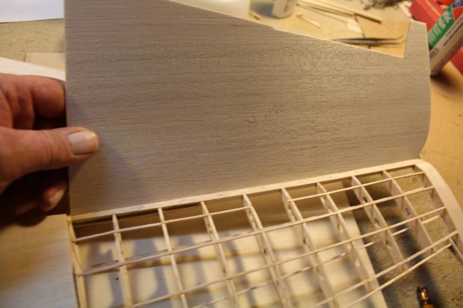
Remember how I’ve often said in the past that I prefer to allow wet balsa/aliphatic resin glue assemblies to dry overnight “whether they need to or not”? Those fuselage skin assemblies DO need overnight drying so I did some work on the wing while waiting. The process I’m using for this Guillow’s Hellcat wing is identical to what I’m doing on the fuselage, but the shape of the wing permits me to work with much larger panels. This is the 1/16” balsa sheet panel that I have cut to fit the upper surface of the right wing. Watch how I keep it under control during assembly.
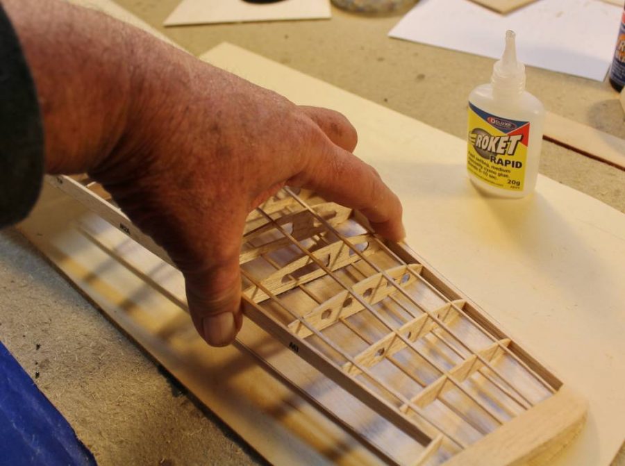
Because the leading edge as I have sanded it to conform with the curvature of the wing ribs forms a straight line spanwise I can use it as a reference platform to keep everything in place and lined up while I do the wet-forming thing. What’s going on here is that I have applied a line of Deluxe Materials Roket Rapid (slow for open assemblies) along the lower surface of the leading edge and pressed the very front edge of bottom sheet into place against it. By holding the assembly together in place for a minute or so I got that fixed reference. Watch how that works…
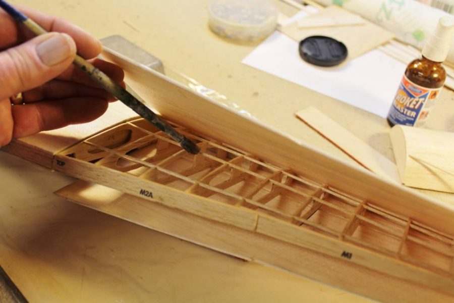
I attached the top surface balsa skin to the upper leading edge in the same way, then sprayed all the sheet balsa with water. What’s happening here is that I’m using a conveniently sized brush to apply a generous coat of Deluxe Materials Aliphatic Resin to every part of the wing structure that’s going to come into contact with the surface panels, and then…
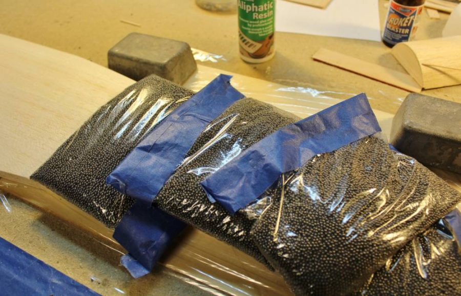
I used several of my custom made shot bag assembly aids to press the whole thing tightly together while maintain even pressure and preventing any movement while it all dries. I tell you more about how I made those shot bags later.
Be sure to check in next month to see how the rest of the build progresses. Until then, feel free to reach out if you have any questio0ns and by all means … check out the links below for all of the equipment used in this column or to peruse the Guillow’s lineup for yourself.
LINKS
GUILLOW’S
DELUXE MATERIALS
COBRA MOTORS
SPEKTRUM
HORIZON HOBBY
The post Master’s Workshop #51: Guillow’s Hellcat RC Conversion Part 2 appeared first on Fly RC Magazine.
Continue reading...
Last month we ran out of page space with all panels of the wing framed up, ready to be joined at the correct dihedral angles to prepare for a sheet balsa covering job that might be a little different from what you are used to. We finished off with a view of the bottom surface of the center section to serve as an example of the way all ribs, edges, etc. have got to blend together without any bumps or discontinuities that would spoil the final surface. Sanding is the magic technique to make that happen, so we will start off this session with more of that.
This is the surface of the wing center section, which has been assembled so far exactly per the Action Plan layout. Note that the bottom/lower 1/16” sq. balsa spars aren’t in place yet. Earlier you saw me doing some rough shaping of the stock kit leading edge with a No. 11 blade; here I’m using my 80-grit sanding block to finish the top surface of the leading edge so that it becomes a flat surface extending ahead of the ribs. The plans suggest that you need to round off the front of the LE. Don’t do that…leave a flat surface like this and on the bottom as well.
You have seen me doing this before. This is the right outer wing panel including the partially shaped modified balsa block tip getting sanded to the same level of accuracy we saw last time on the bottom of the center section.
Now we are going to make some serious modifications to permit mounting a set of E-Flite 10-15 90 degree rotating retracts. I have already established to my satisfaction that a slightly smaller Guillow’s fighter (the Kit. No. 403 Spitfire) will fly well with the ordinary side-rotating E-Flite retracts, so we know this is going to work. Note: I have checked out many mechanical, pneumatic and electric mini-retracts. What I’m sharing with you here is the smallest, lightest RLG installation that I feel I can trust for real-world flying. If you are aware of a commercially available system that you believe might work better, please let us know about it.
Back to wing modification. I made 1/64” aircraft plywood doublers for F-3 and F-5 that fit on each inside face of the respective ribs to serve as hard mounting surfaces for the RLG mounting blocks I’ll show you next. ALSO NOTE: If you include this modification on your Guillow’s Hellcat you will discover that there’s a lot of cut-and-fit work involved. The important measurements to get right are the position of the upper retract pivot point, the forward rake built into those mounting blocks, and the length of the strut. Make all this stuff match the Guillow’s Action Plan as closely as you can.
There are four RLG mounting blocks that I cut and shaped from medium-weight balsa block. You may be able to see some of my changes marked on the plan in pencil as well. Watch how this comes together and it will all make sense.
This modification puts the inside/upper portion of the retract units so close to the inner face of the top wing skin that I chose to add some extra reinforcement to the front of the landing gear bay. I cut this 1/64” plywood doubler plate to fit flush with the top/outer edges of ribs F-3 and F-5. If you study the image you’ll see how it’s going to fit into place. NOTE: By the time we have removed enough balsa for the mounting blocks and RLG units to fit there’s not much left of rib F-4.I left that rear upper edge in place to help locate the sheet balsa wing skin that’s coming later.
Having measured and marked all the dimensions and clearances carefully, I located the mounting screw holes in each of the blocks with them outside the airplane. The reason for this is to ensure that each RLG unit fits square and true against what will become its mounting base plate. You can trim the outer dimensions of the assembled RLG/block units as needed to fit the wing structure correctly. If you install the blocks first you risk having them line up with the RLG units incorrectly, which will cause stress and possible failure.
See how it all comes together? We’ll worry about those over-length struts later.
Same game from above. If you study this assembly carefully you can work out how I’ve attempted to distribute the landing loads over as much of the original, pre-modification wing structure as possible.
My next step was to remove the RLG units, assemble the various wing sections in place on the Guillow’s Action Plan, and join them per the kit instructions.
With all the material I removed from the original structural design it was necessary to replace some of the strength that went with it. I made a pair of new leading edge doublers from 1/32” plywood, cut appropriate clearance slots between the front of each affected rib and the inside face of the leading edge and assembled it all with Plenty of Deluxe Materials Aliphatic Resin glue. NOTE: After shooting this image I secured each spar/leading edge assembly with some of those modified heavy duty clothespin clamps you have seen before.
I decided to fully cover/enclose the wing center section with 1/16” sheet balsa before putting the entire wing assembly aside to work on the fuselage. This is the bottom surface sheet cut as nearly to exact shape as I can get it before assembly. I’m going to use an unusual technique to attach the sheet balsa covering, which I’ll describe a bit later.
With the wing structure set aside for a while I’m going to start work on the fuselage to get it caught up with the rest of the airplane. All the fuselage center keel parts (A-1 through A-5) are assembled exactly per the Guillow’s Main Plan. In addition to that first step I have glued fuselage former B-1 in place perpendicular to the assembled keel parts. Unlike the pair of laser-cut Kit. No. 403 Spitfires I told you about in my lead article on Guillow’s kits, this Hellcat along with the other four 1000 Series kits is still a die-cut product. Like most of Guillow’s other scale model designs, this one uses a fuselage structure based on a vertical center keel which is assembled from several die-cut parts and then “filled out” with a series of balsa half-formers that define the left half of the structure. What’s happening here is that I have assembled the keel in place over the fuselage layout on the Main Plan and added the left side of half-former B-1.
Before we go any further let’s take a closer look at a representative die-cut fuselage former. This is B-8 (the first former behind the wing trailing edge). Remember that we have already explained Guillow’s willingness to replace any die-cut parts sheets of questionable quality? This 1/16” sheet part is cut from balsa that’s OK for this application, but there are some things we can do to improve it. Can you see the slightly uneven, soft-looking cut on the corner of the former away from my thumb?
Sanding is the cure for this little piece of balsa’s shortcomings. First I flat-sanded each face of the part down to 220-grit smoothness while removing about 1/64” of thickness and weight…
…and then off-camera I turned the former on-edge and used that same sanding block to clean up any sloppy edges I could find. Here you can see half-formers B-1 and B-2 finish sanded and glued in place on the keel.
The next several steps in fuselage assembly go exactly per the Guillow’s kit instructions. Here you can see half-formers B-1 through B-11 assembled in place to define the left half of the fuselage. The “extra” parts at the rear are for the right side half-formers and fuselage side keels.
The next step, again following the Guillow’s Main Plan and instruction/assembly guide, is to glue the two left side-keel pieces (A-5 and A-6) into a single unit and then slip them into place in all the formers. Notice here that I am using a single-edge razor blade to trim the side keel notch in B-8 for an exact fit. When building a die-cut kit such as this one you have to be ready to adjust any of the pre-cut slots. In this case the notch centered about 3/64” too low with the result that the side keel had to bow out of line to fit into it. It’s up to you as a responsible model builder to make these simple corrections whenever you find the need for them.
Fully assembled in place the corresponding right side keel looks like this. If you look carefully you’ll see that I have traced and cut out doublers for the top portions of B-2 and B-4. This is a departure from the Guillow’s plan that becomes the first step in creating a removable battery pack access hatch. Can you see the squared-off cutout in B-3 that aligns with the bottom of those new doubler formers?
The next step in modifying the standard fuselage for that hatch is to install two inset 3/32” balsa sheet rails as you see here on both sides of the fuselage. These rails, which become edges/liners for the hatch and cutout, are glued to everything around them, but NOT to each other.
Now I’m using a 120-grit sanding block to trim the outer faces of those assembled hatch rails flush with the outside edges of all the surrounding formers.
The next step, this time right in line with the standard kit assembly sequence, is to install all the 1/16” sq. balsa fuselage stringers. Here again is a situation that will very probably require you to do some trimming of the die-cut stringer notches to ensure that all the stringers line up on-center, straight, and evenly spaced from their neighbors. If there’s any doubt dry-fit a stringer in place and sight along it end-on. Any waves or wiggles you can see have to be corrected by trimming those holes. Here I’m using a custom tool that I made for this job. The piece of wood in my hand is a length of 1/16” plywood with a carefully-cut 1/16” wide strip of 120-grit sandpaper glued along each of the long edges. Aligned with what should be the exact location of a series of stringer notches, moving it back and forth in a sawing motion will leave neatly-cut notches just where the plans say they should be.
Here’s another look at the same process with several top stringers located and glued into place. NOTE: Follow the instructions that come with then kit and always install stringers IN PAIRS…right, left, right, left etc. At this point in its assembly a fuselage structure like this one is pretty floppy and at risk of being permanently twisted if you don’t keep the stringers from adding unbalanced stresses as you install them.
Here’s another significant modification from the original plan. As designed, former B-7 is flat/straight from top to bottom. If the model is built that way, with the wing permanently joined to the fuselage, this doesn’t matter. BUT, with a removable wing such as we are going to use there are two new issues to deal with. First, with the leading and trailing edge formers (in this case B-3 and B-7) are left flat, the process of inserting/assembling the wing into the finished fuselage will be a fussy job of keeping everything perfectly in alignment AND you won’t be able to use a dowel stub at either the leading or trailing edge per usual RC practice because there won’t be any way to rotate the wing into place to insert it. Second, if the model ever hits something you didn’t want it to…OK, we won’t use the “C” word…the beveled/angled rear face of the wing cutout that’s created by angling the bottom of B-7 will give it room to “knock off” without taking a lot of the rear fuselage with it. Also, did you notice that here I’m using a razor blade to cut stringer notches that line up with the rest of the formers?
Once again while you weren’t looking I added an extra part…in this case a duplicate former B-2 cut from 1/16” aircraft plywood. This is going to take over the function of the plywood former/firewall that was originally designed to attach to the front of B-1. In recent Guillow’s kits several 1/16” plywood parts have been replaced by a die-cut sheet of white vinyl material. I cannot recommend that you use any of this stuff. Not only is it less dimensionally stable than the plywood it’s supposed to replace, it’s three to four times heavier than an equivalent plywood part. With all that said, the new B-2 doubler plywood firewall must have all those stringer notches cut into it to match B-2, This is not a job for a lone unsupported razor blade. If you can measure out and mark the notch positions you can pre-cut them on a scrollsaw before assembly OR you can use the edge of a Dremel grinding disc like this to do the slotting in place.
With all the formers and 1/16” sq. balsa fuselage stringers in place it’s time for some serious sanding. We are going to create a very closely-fitted sheet balsa skin over this surface, and any bumps or other errors WILL show through. Another note…if we were planning to retain the open structure…tissue covering over open stringers…I would “scallop” the formers between each pair of stringers to avoid that poked-through “starved horse” look that results from leaving those rounded-off outer edges to protrude. But, since we’re going to use balsa sheet covering which creates and maintains its own curvature, we are going to leave the formers as designed to help that balsa sheet assume the curved “round” shape we want for this airplane.
The next step in this process is to measure and cut out the actual sheet balsa panels that are going to become part of the fuselage. I’m going to use the best quality light 1/16” balsa sheet I can find. This not something Guillow’s currently includes in their kits. Why 1/16” and not something lighter like 1/32”? In a word, SANDING. Balsa sheet slightly thicker than we want the finished fuselage skin to be is the answer. The extra thickness provides material to “sand on”, to blend less-than-perfect panel edge joints along with any other errors that are going to appear in a job like this no matter how carefully we work. What you see here is one of the ordinary bond paper patterns I made to fit specific sections of the fuselage. The criterion here is that the dimensions/size of each panel must allow it to be attached creating only single-curvature bends.
Like here. What you see here is two separate 1/16” balsa sheet skins that meet/join along the bottom fuselage keel. I wet each piece thoroughly with plain water and then attach it with Deluxe Materials Aliphatic Resin glue, which is water-based. You’ll get a closer look at how I do this in a bit. Masking tape is the best way I have found to keep sheet skin like this in place while everything dries without damaging it the way pins would.
I can’t work on the adjacent tail panels with all that tape still in place so I went to the front instead to attach more of that 1/16” balsa sheet skin over then portion of the nose that’s going to become the removable battery hatch. Here it’s easy to see how that masking tape holds the wet balsa sheet and still-wet glue precisely in place.
While I was waiting for these two “wet balsa” layups to dry I decided to work on the cowl. This is going to turn out to be very different from the original Action Plan design, but I’m going to base it all on the standard Guillow’s molded plastic cowl. You can pretty well see “just looking” how I prefer to trim parts like this from their matrix sheets. I doubt that I could come as close to the accuracy I’m getting here using scissors or a blade.
Remember how I’ve often said in the past that I prefer to allow wet balsa/aliphatic resin glue assemblies to dry overnight “whether they need to or not”? Those fuselage skin assemblies DO need overnight drying so I did some work on the wing while waiting. The process I’m using for this Guillow’s Hellcat wing is identical to what I’m doing on the fuselage, but the shape of the wing permits me to work with much larger panels. This is the 1/16” balsa sheet panel that I have cut to fit the upper surface of the right wing. Watch how I keep it under control during assembly.
Because the leading edge as I have sanded it to conform with the curvature of the wing ribs forms a straight line spanwise I can use it as a reference platform to keep everything in place and lined up while I do the wet-forming thing. What’s going on here is that I have applied a line of Deluxe Materials Roket Rapid (slow for open assemblies) along the lower surface of the leading edge and pressed the very front edge of bottom sheet into place against it. By holding the assembly together in place for a minute or so I got that fixed reference. Watch how that works…
I attached the top surface balsa skin to the upper leading edge in the same way, then sprayed all the sheet balsa with water. What’s happening here is that I’m using a conveniently sized brush to apply a generous coat of Deluxe Materials Aliphatic Resin to every part of the wing structure that’s going to come into contact with the surface panels, and then…
I used several of my custom made shot bag assembly aids to press the whole thing tightly together while maintain even pressure and preventing any movement while it all dries. I tell you more about how I made those shot bags later.
Be sure to check in next month to see how the rest of the build progresses. Until then, feel free to reach out if you have any questio0ns and by all means … check out the links below for all of the equipment used in this column or to peruse the Guillow’s lineup for yourself.
LINKS
GUILLOW’S
DELUXE MATERIALS
COBRA MOTORS
SPEKTRUM
HORIZON HOBBY
The post Master’s Workshop #51: Guillow’s Hellcat RC Conversion Part 2 appeared first on Fly RC Magazine.
Continue reading...