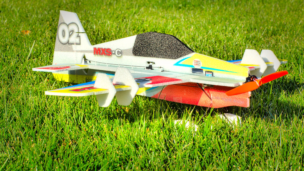
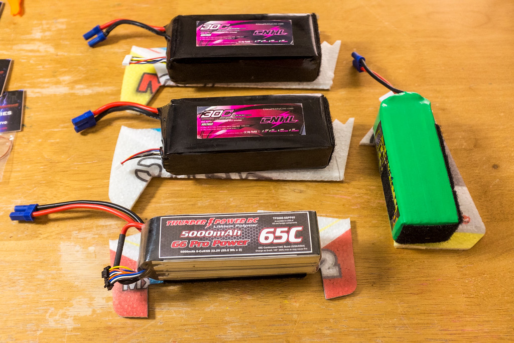
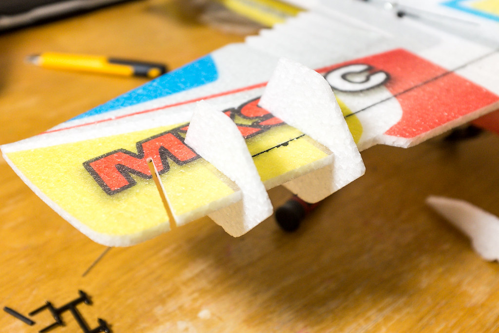
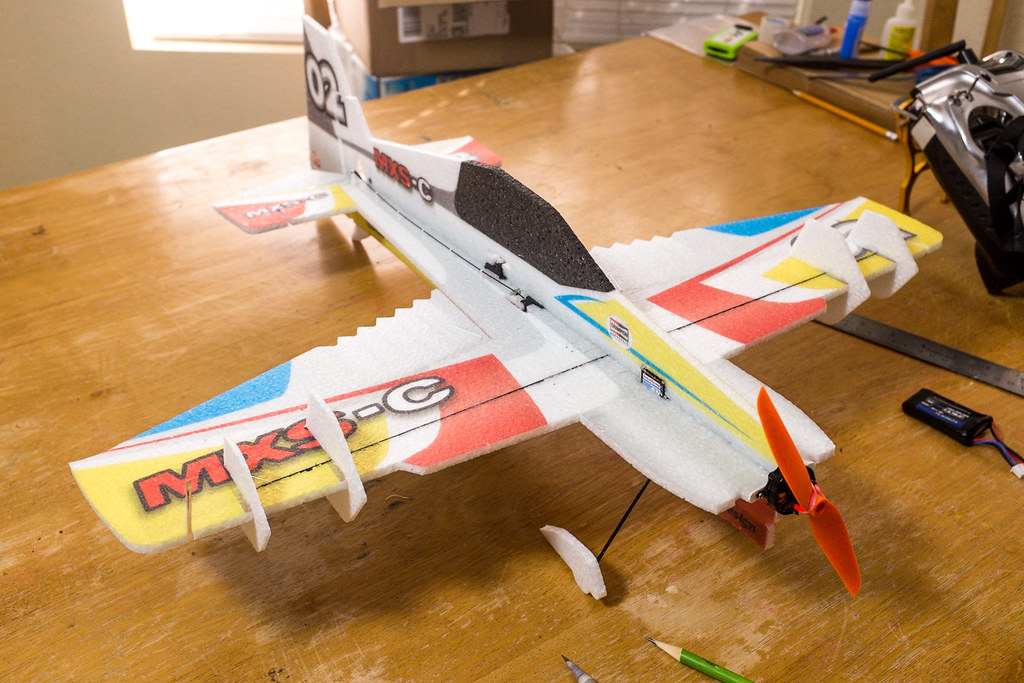
So Let's Get This Build Started
[video=youtube_share;njY4mACNTVE]http://youtu.be/njY4mACNTVE[/video]
Video Overview, With Some Built Tips.
Before you get started, you need to inventory all the parts and test the electrical components. The last thing you want it so be done with the build and have to wait a few days for replacement parts. Also by checking your power system parts, it may save you some money because after the parts are installed, it may void the warranty.
Flex and weigh down your control surfaces, this is a very very important first step on any EPP foam model. This will help to defeat the memory in the foam at the hinge lines. This will insure you can achieve maximum deflections, as well protect your servos against over stressing which can shorten the life of the servos.
[video=youtube_share;YNxdMB4Ji0E]http://youtu.be/YNxdMB4Ji0E[/video]
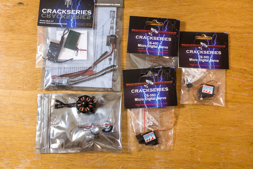
Crack Power combo.
You will need one 4 gram servo for the ailerons, and two 3.5 gram servos for the tail surfaces. You will need a 6 amp esc, and a 12- 14 gram 2000-2300 KV 2S motor. You will need a receiver (in my case its DSM/2), and a prop 6x3 to 7x3.5 GWS DD.
[video=youtube_share;JZOlDuWCj9A]http://youtu.be/JZOlDuWCj9A[/video]
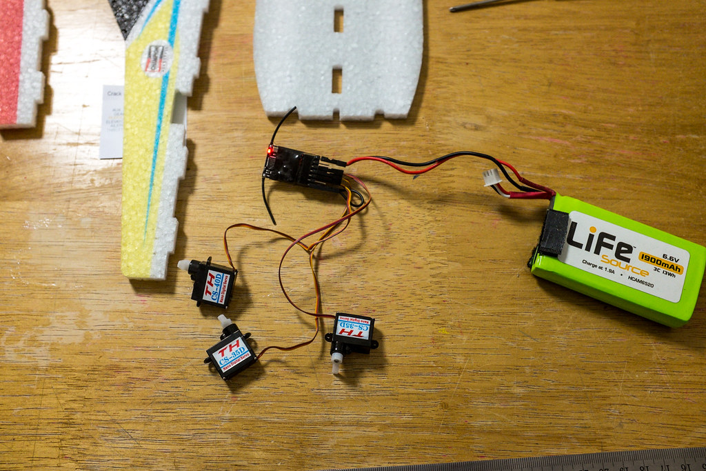
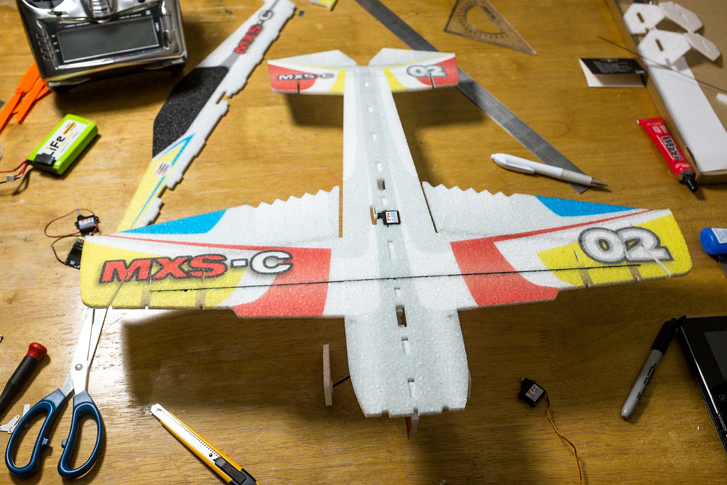
After you lay out the foam on the table, look at closely and try to determine how to orientation of the servos. This is a good time to test all the components making sure they are all working as they should. I promise this is a critical step that will save you time and money. A quick word on the power combos that come from Twisted Hobby's, they are awesome! I highly recommend them, they are the correct weight, tons of power, and best of all they perform wonderfully. Also the offered power combos save you lots of time searching and hoping the stuff you buy will work when you finally get it. Seriously consider buying a TH power Combo, you wont regret it.
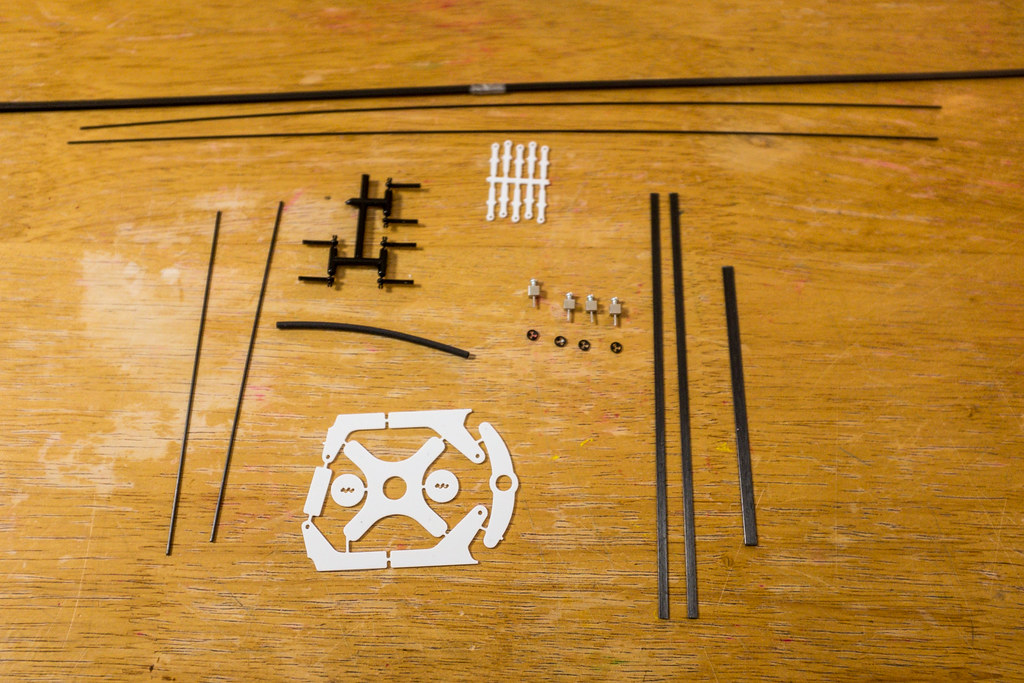
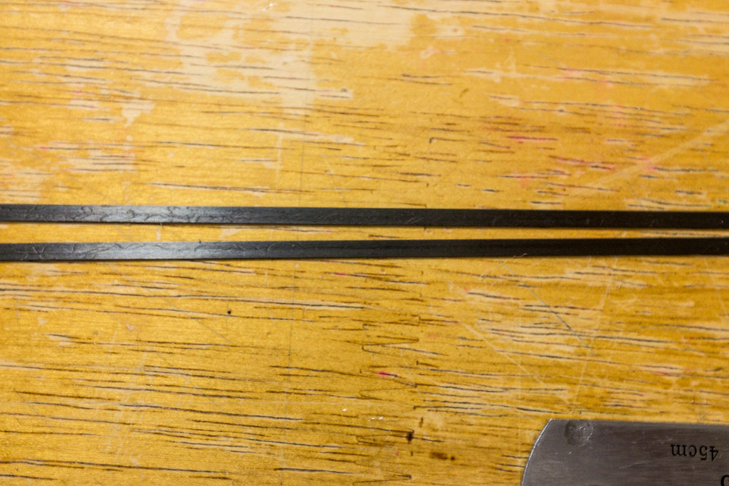
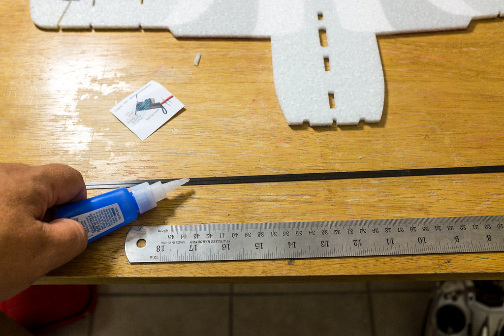
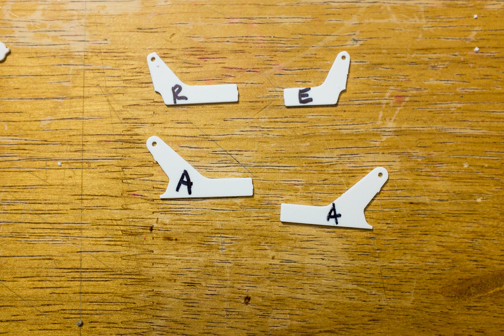
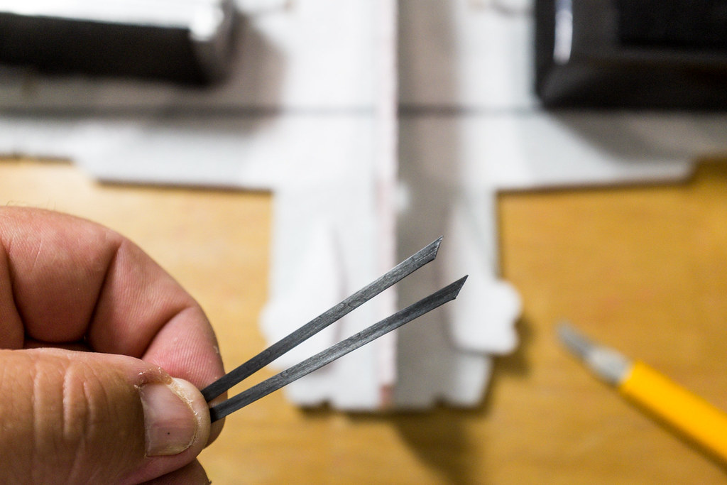
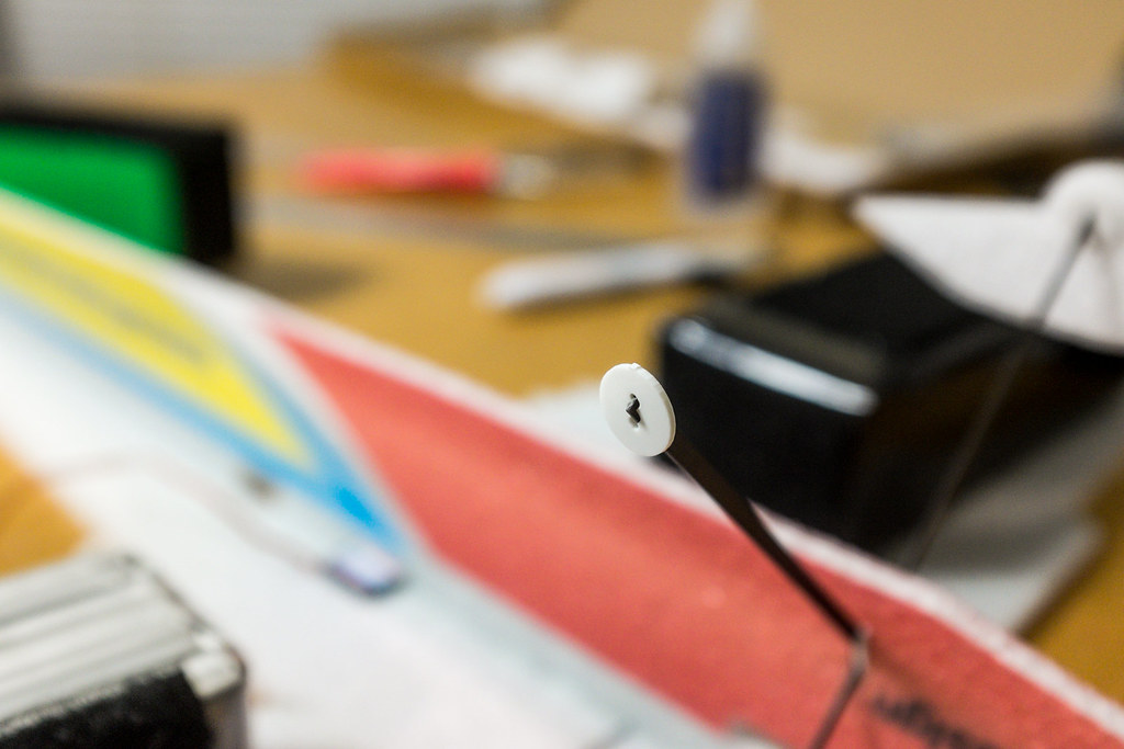
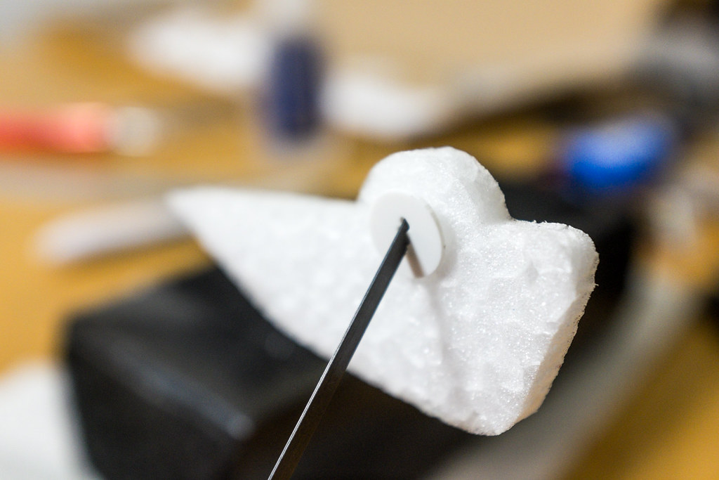
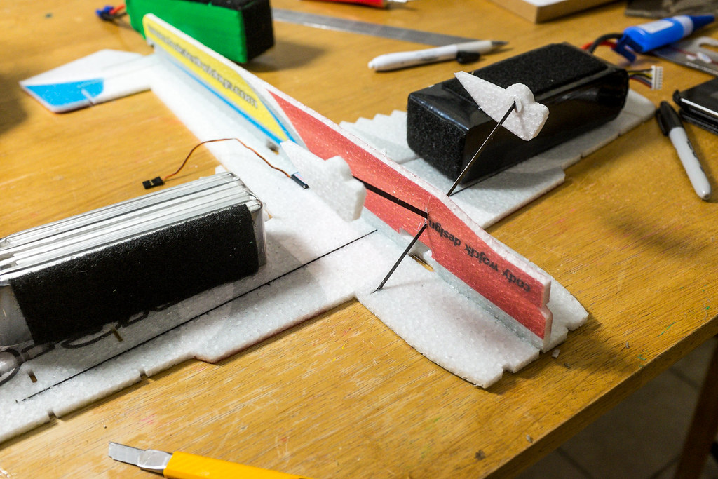
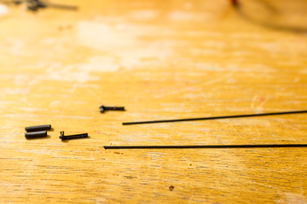
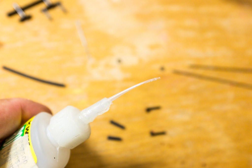
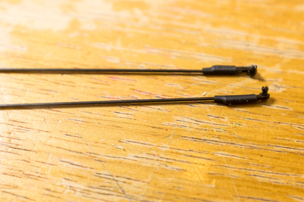
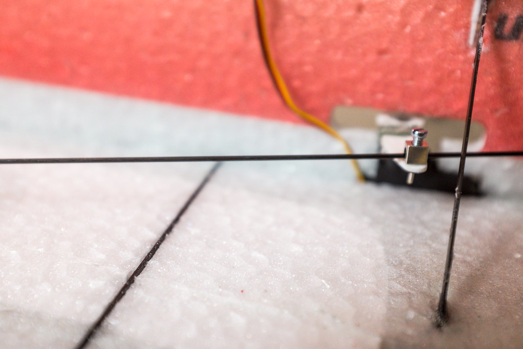
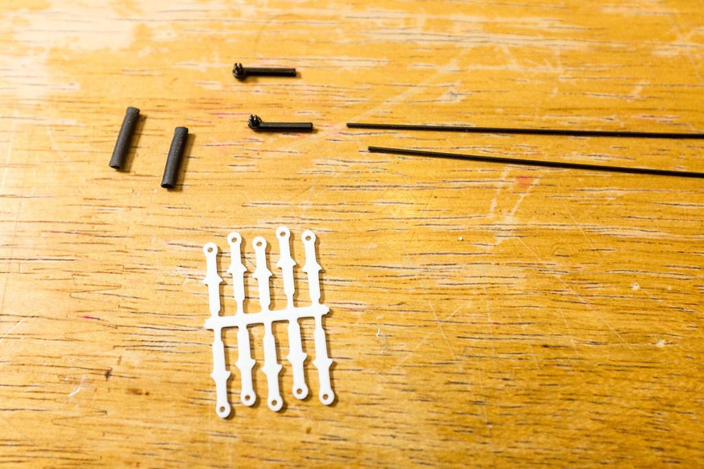
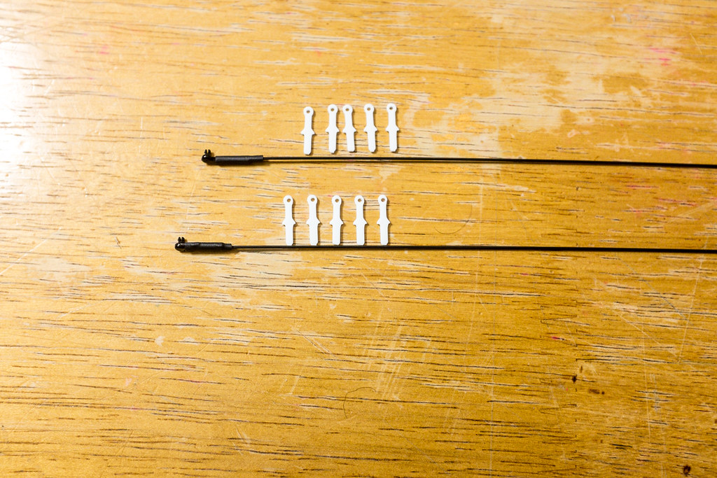
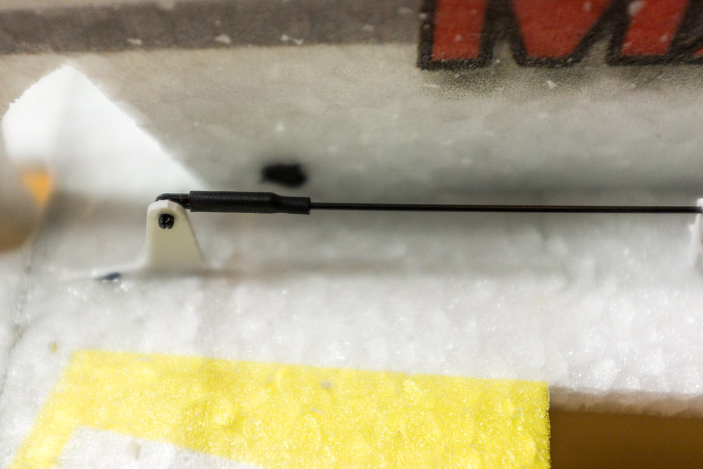
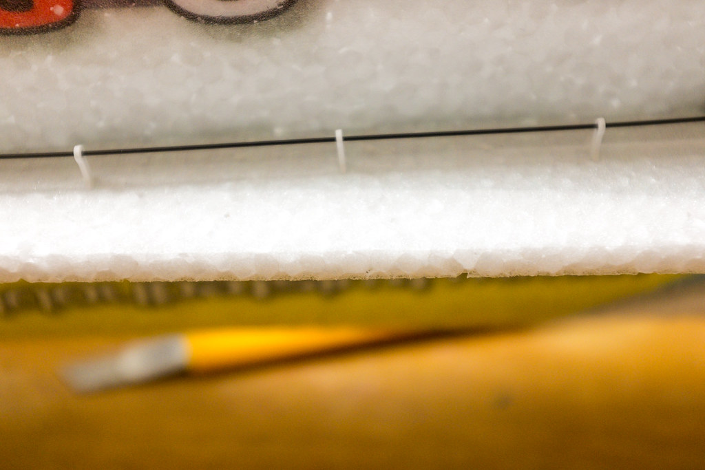
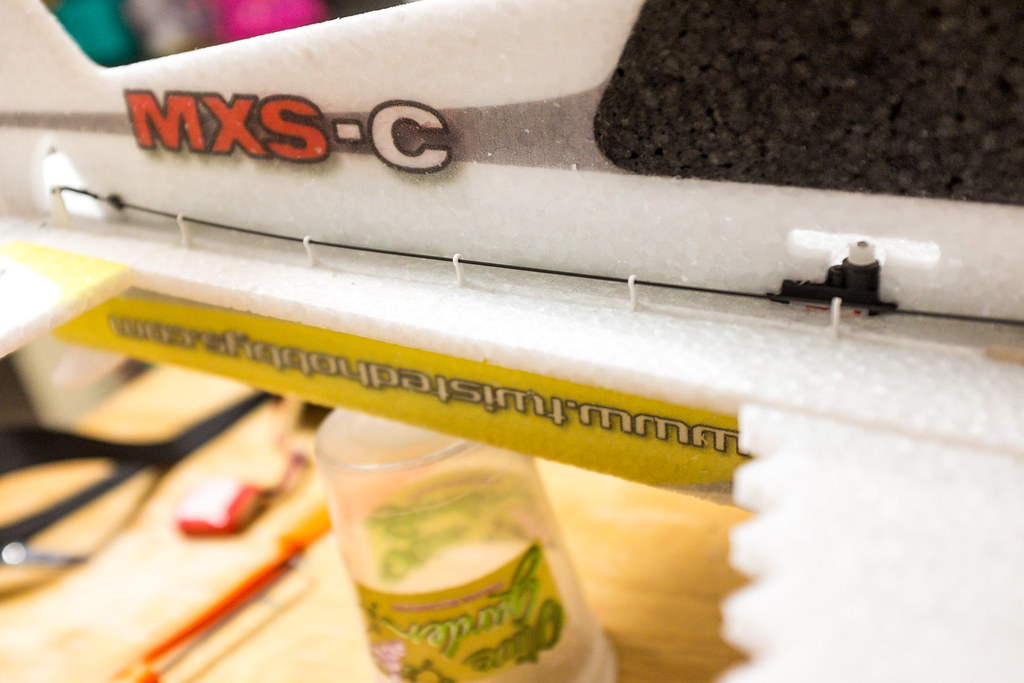
Here is a look at all the rest of the parts you will be needing to build your model. On the left you see two carbon round rods, these are the aileron push rods. The white parts to the right are the control horns, motor mount, landing gear brace, and wheel pant supports. The little black tube directly above the control horns is a heat shrink tube for slipping over the snap locks. The snap locks are the black molded looking parts above the heat shrink, they attach to one end of each control rod with ca, and heat shrink tube. The little white double row of tiny dagger looking parts are the tail surface push rod guides. Below them are 4 silver blocks, these are to be mounted through the holes of the servos control horns and held into place with the little back clips below them (the screws holds the control surface carbon rods in place. To the right of them are three flat carbon strips, the two longer ones are the landing gear legs, and the smaller one is the elevator cross support/stiffener. The two carbon rods above the tail surfaces rod guides, are the tail surface control rods, and the package of carbon at the top is the main wing spars (two flat very long strips). Man that was a mouth full, but I hope you get the idea.
This little model is a lot of fun to build, take your time, and follow the manual and this build thread and before you know it, you will be up and flying.
[video=youtube_share;LjSyU050ugU]http://youtu.be/LjSyU050ugU[/video]
The Vertical Fuse Build.
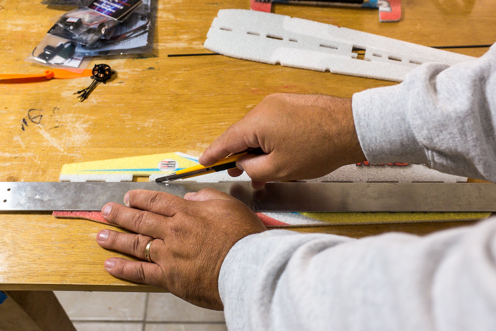
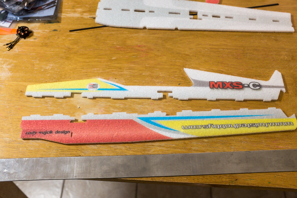
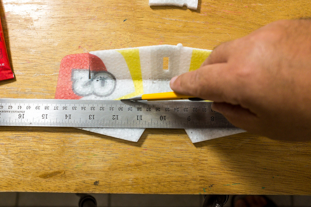
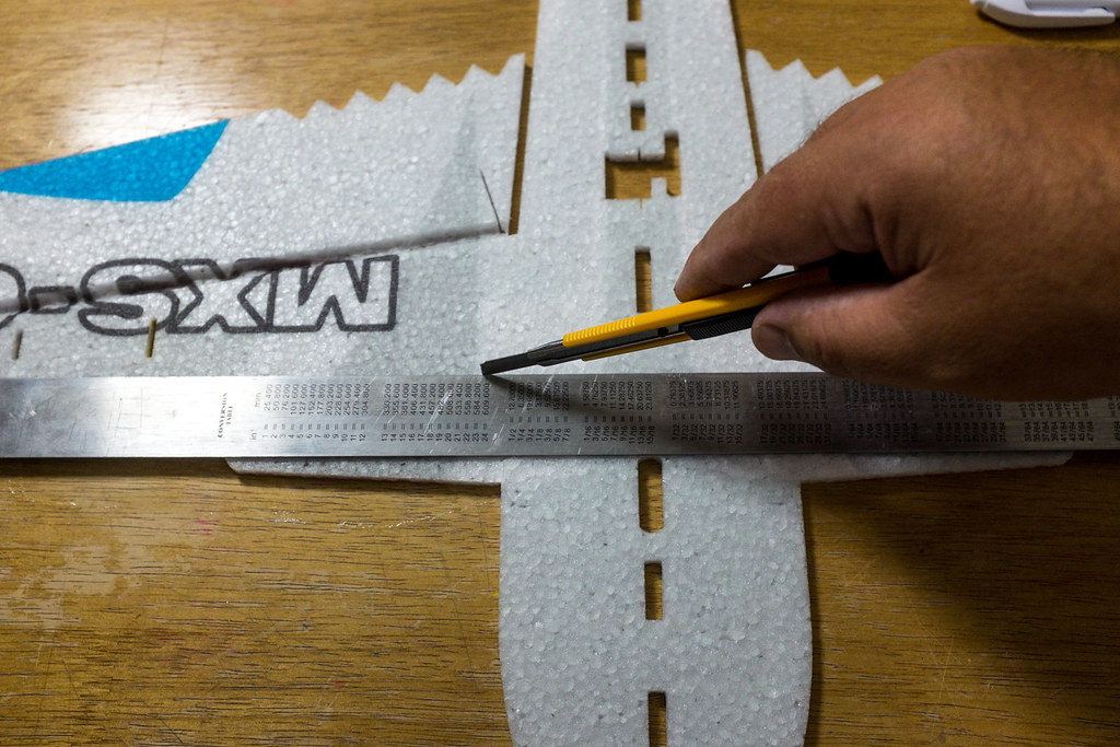
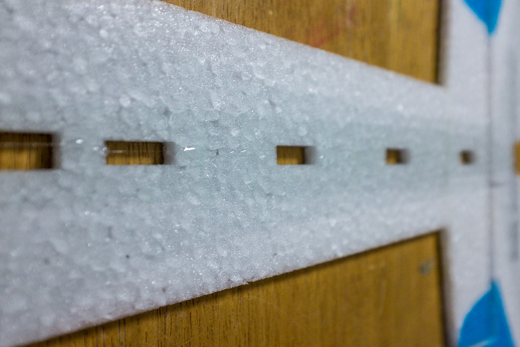
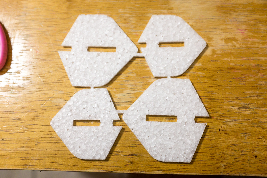
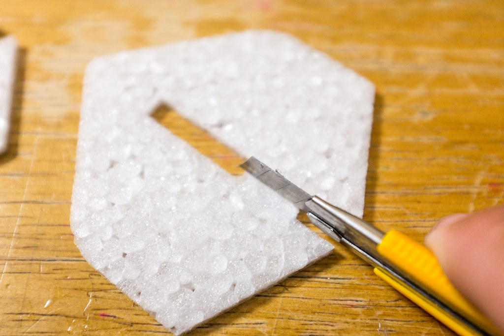
We need to cut the vertical fuselage in half. The good news is it's real easy to line up and cut the vertical fuse into two pieces. The factory cuts in these little mouse house indents in the center of each rectangular opening. Use these indents along with a long metal straight edge and a sharp razor to cut the vertical fuse in half.
[video=youtube_share;YuknsHCqAvY]http://youtu.be/YuknsHCqAvY[/video]
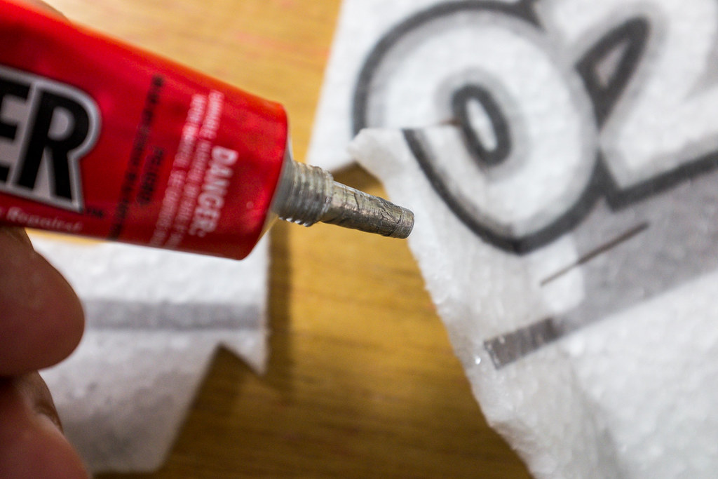
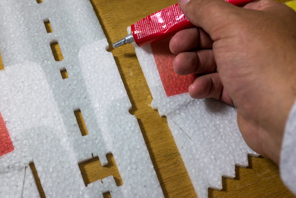
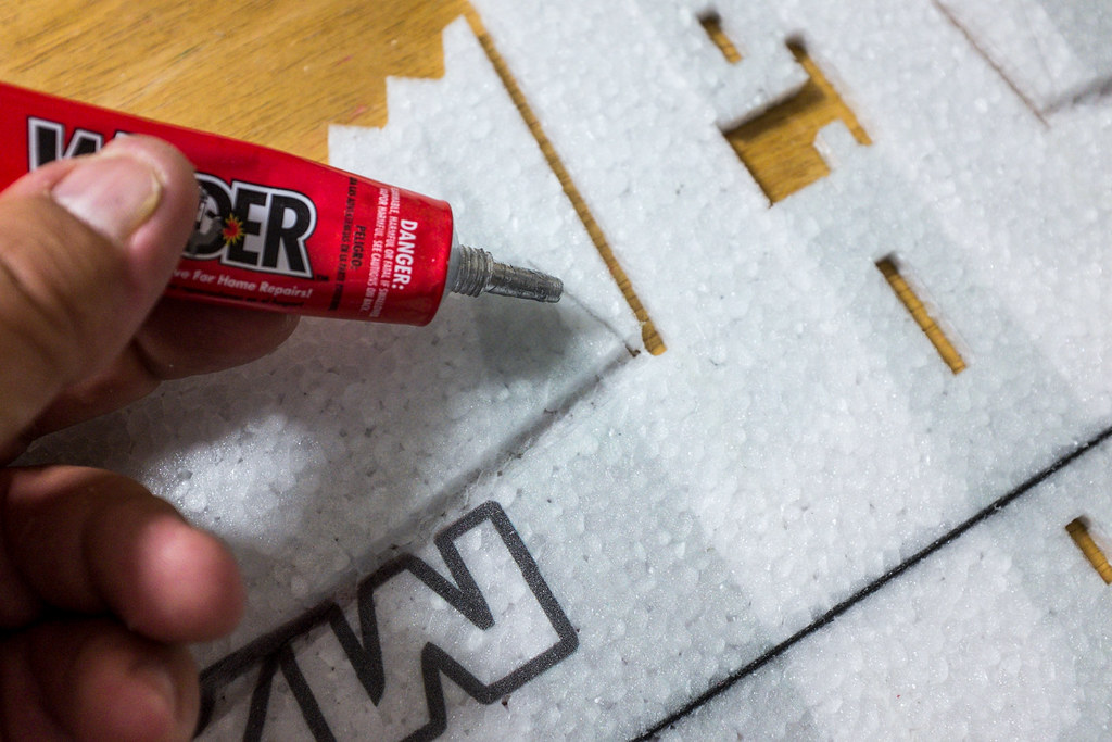
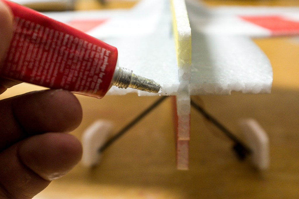
Next locate the black canopy piece, and use welders glue to attach it on to the top vertical fuse half. Wet both contact surfaces with glue, press them both together wet, then pull them apart and wait until both surfaces are dry to the touch, this will take 4-10 mins. Once both glue surfaces are dry to the touch, carefully press them together on a flat surface, and rock the two pieces back and forth to make sure the edges of the seam are nice and adhered (Let this be known as the, "Dry Welders Method") What's important is to make sure that canopy and top fuse are flat and appear to be a single unit.
[video=youtube_share;DaILjVhYdVc]http://youtu.be/DaILjVhYdVc[/video]
Video Tip, How to use Welders
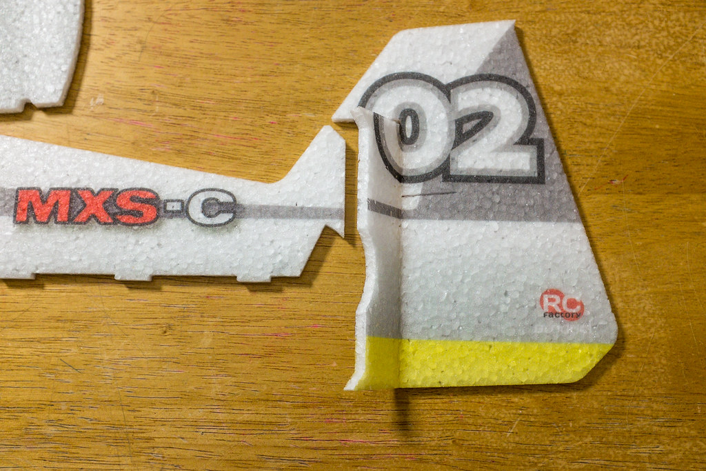
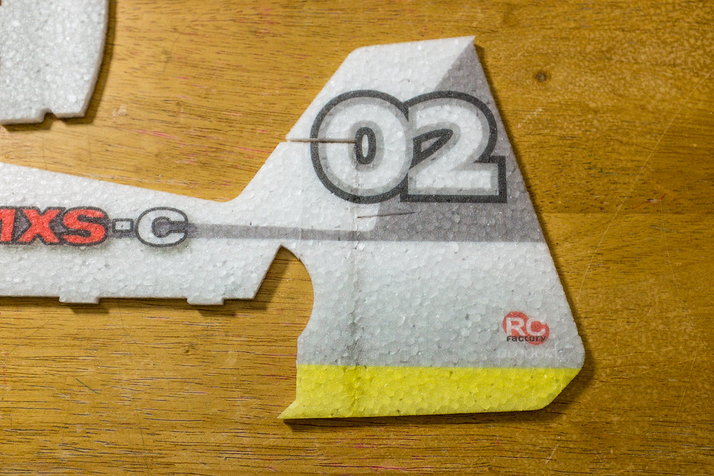
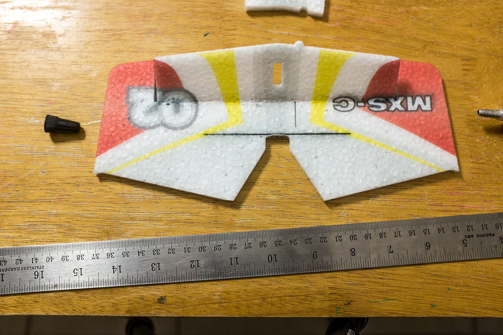
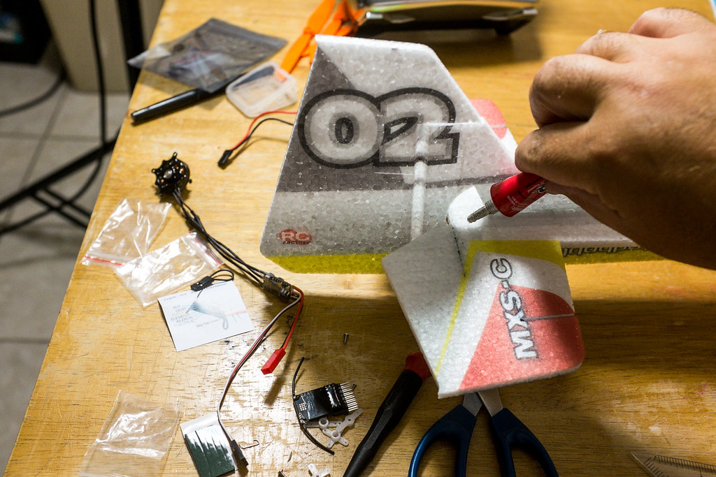
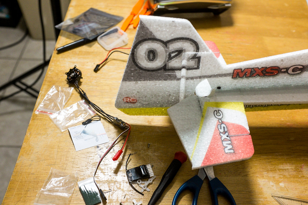
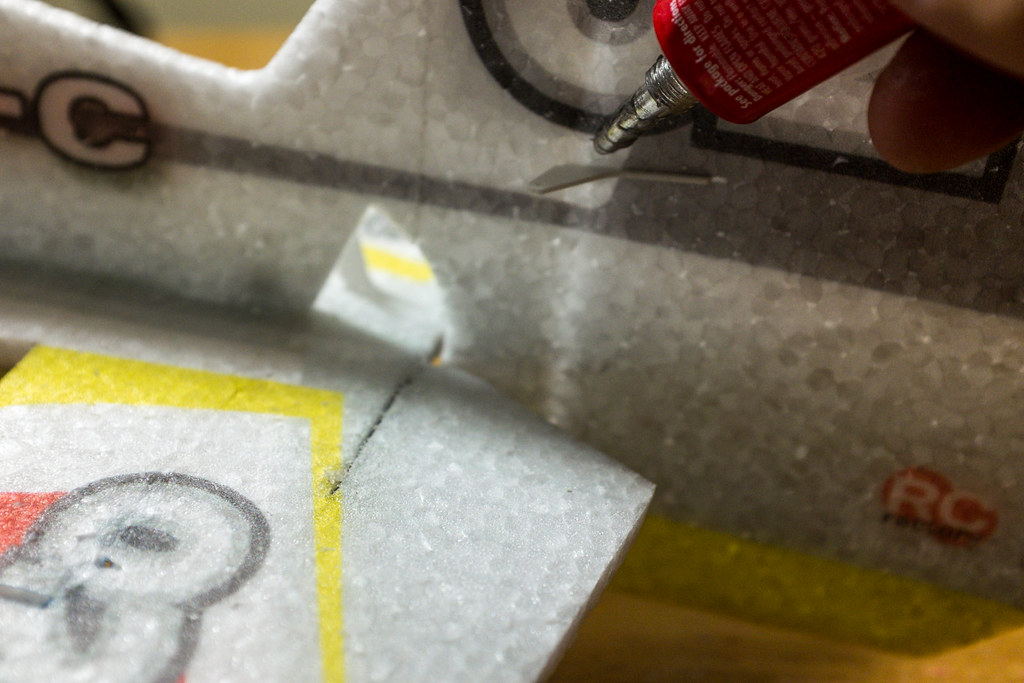
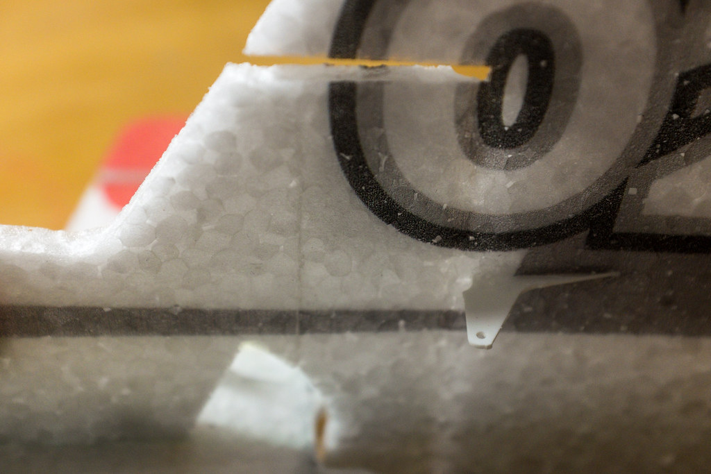
Now collect the rudder, and repeat the same gluing process as we did with the canopy (dry welders method). Make sure the to use the factory cut lines to line up the rudder. Make sure you leave a parallel, but small gap between the rudder counterbalance and the top of the vertical stabilizer.
If you use the cutout of the elevator travel slot, and the top if the vertical stab, lining up the rudder is easy. When you are don't it should look like the image above.
The Horizontal Fuse Build
Grab the elevator and look closely to see a little pre-cut line that runs along the elevator. Use that pre-cut line as a guide and with a metal strait edge and a razor knife, open it all the way up from top to bottom. The cut will become a slot for the flat carbon stiffing strip.
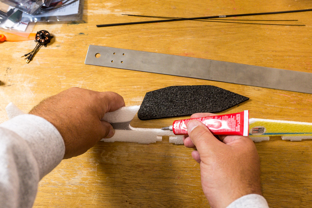
Now hold open the cut slot, being careful to not tear the thin strip that bridges the two elevator halves and fill it with a bead of Welders glue. Also you want to sand both faces of the flat carbon strip. Just rough the surfaces with 120 grit or so, it makes sure the glue bonds well. When you glue this we will do it a little different that the dry method. Wet up both inside surfaces of the cut, and the carbon strip. Slip the Carbon strip into the cut slot and press everything tight. Have a paper towel ready to clean if the glue that squirts out, then pull it back apart, removing the carbon strip.
Now let the glue tac up just a little (1 to 2 mins) holding it apart. Next, slip the flat carbon strip pack into the slot and press the seam tight together while holding everything flat on a table. Let things sit for 3 to 5 mins longer and the glue will start to dry, re-press the seam together and it should hold tight.
If you try to use the dry glue method, you run the risk of making a mistake with the glue bonding the slot together and the strip not being exactly flat and in place. What you will end up with is an elevator that's warped or cocked at some weird angle. You will use this same wet method later on when you install the main wing spar.
Glue On The Elevator & Wings To the Horizontal Fuselage
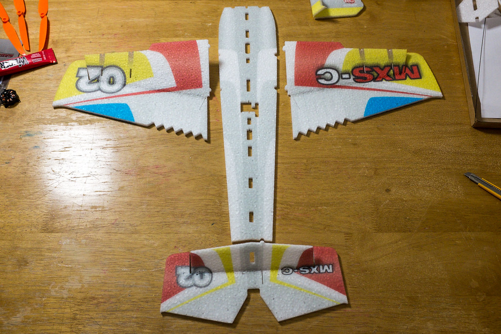
Installing the wings is pretty easy, but first you need to make sure the horizontal fuselage is facing up. With the nose of the fuselage facing away from you, make sure the slot for the elevator servo is to the right. Now use the Welders Dry glue method to glue the wings to the fuse. It's easy, with the fuse facing up, and the aileron hinge slots down, use the indents on the fuse and the tabs on the wing root to line everything up.
Now glue the elevator/horizontal stab on in the same way as you did the wings. Make sure the hinge slot down is facing down, wet up both joints, press it together, pull it apart, let it dry and press it back together. Rock the seam back and forth on a flat table as you apply pressure on both sides of the seam.
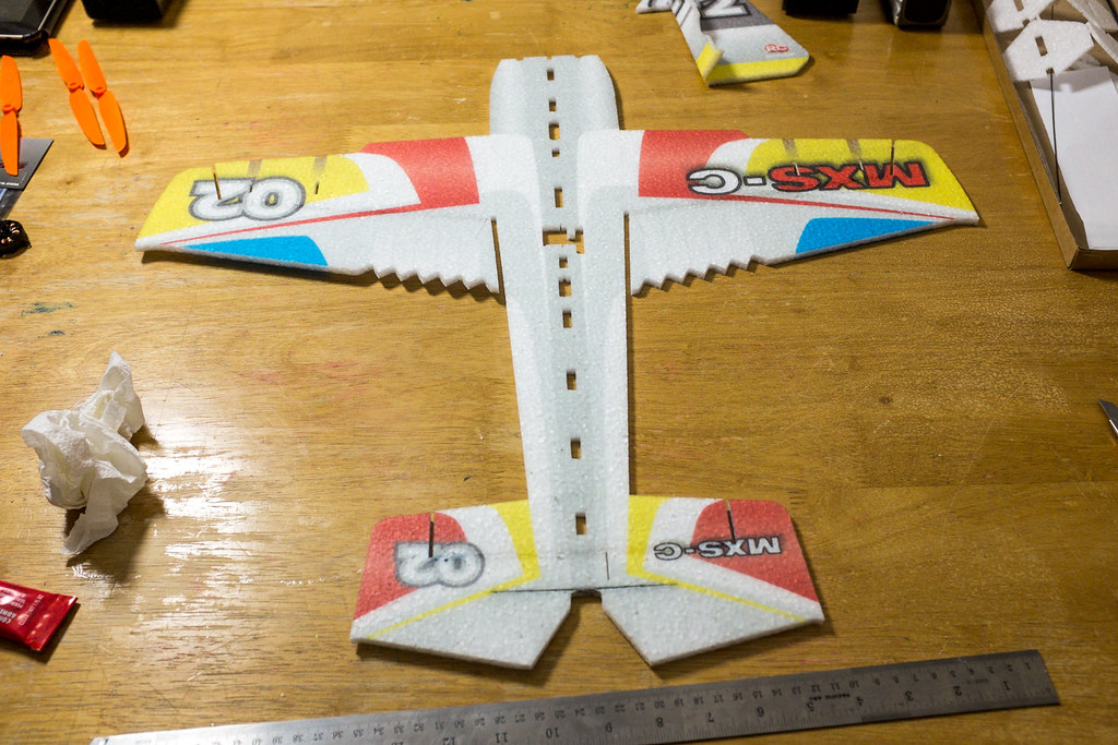
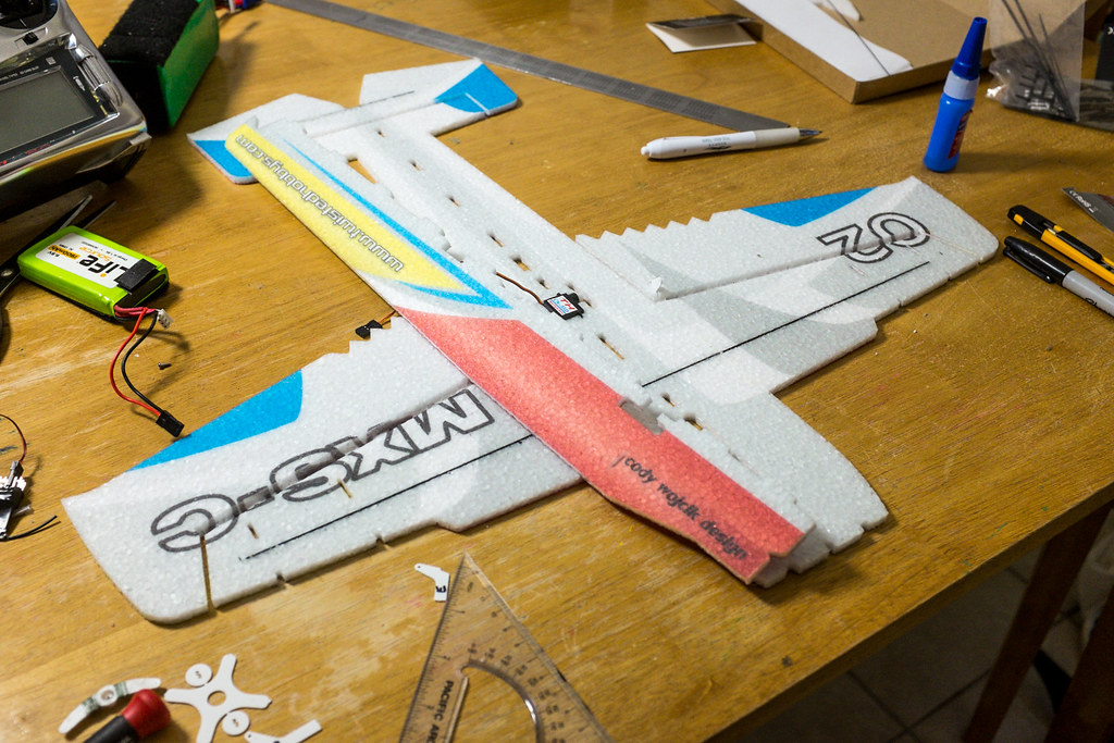
If you did everything correctly, this (pic directly above) you should have a complete wing, fuse, and elevator assembly that looks just like this.
Setting Up The Main Spar
Install The Aileron Control Horns
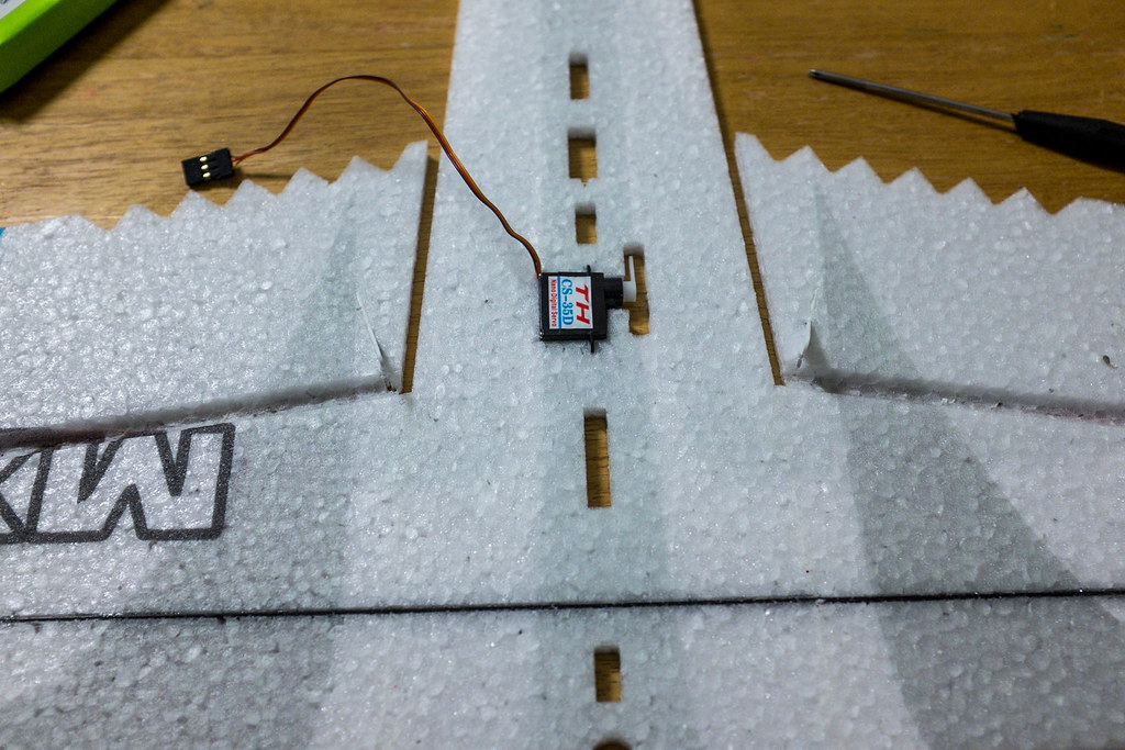
Slip In The Elevator Servo
Install The Lower Vertical Fuselage
Install The Landing Gear
Stand It Up
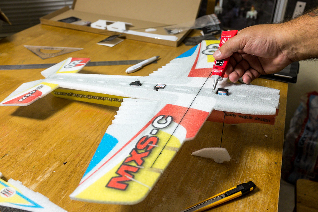
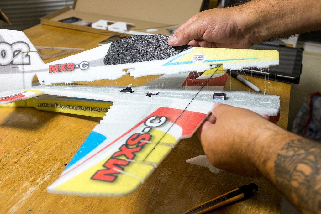
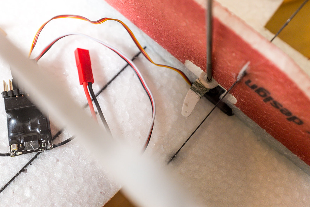
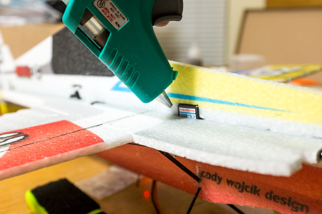
Drop in the Aileron servo and lay down some glue for the top vertical fuselage.
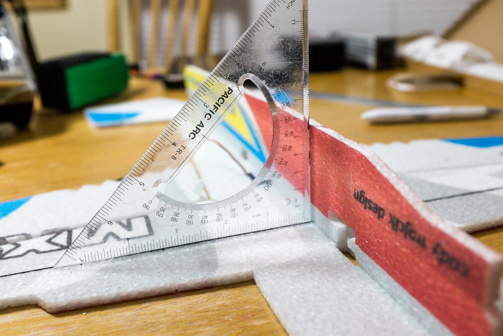
Use the Dry Welders method. Also remember to slip in the rudder servo. (dont glue them in just yet). Also use a sure to make sure the top fuse is 90° to the horizontal. Also line up the rudder opening carefully, it needs to be straight to avoid coupling issues.
Glue in the tail skid (dry method).
Place it as shown here in this image.
Install The Tail Surface Control Horns
The control horns for the tail are easy to identify, they are the only two left

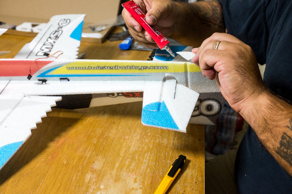
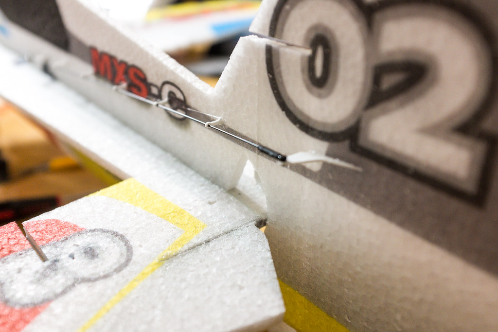
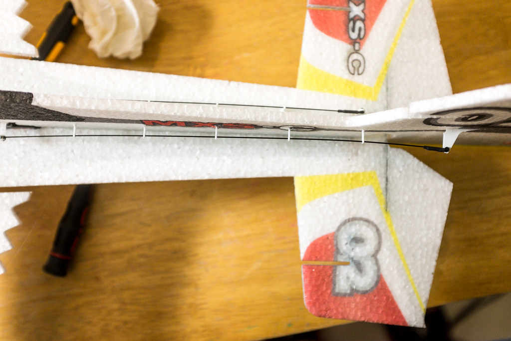
Wet the slits, and the base of the horns with welders. Slip them in place and pull them out. The the glue tac up for 2-3 mins, but not fully dry (wet method). Then slip them back into place and make sure the tip of the horn is in the middle of the hinge line, and allows for full deflection before they bottom out of the fuselage.
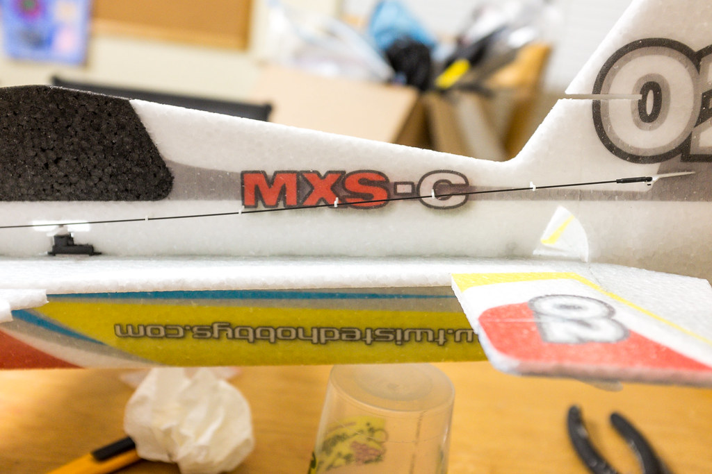
Proper alignment of the rudder horn.
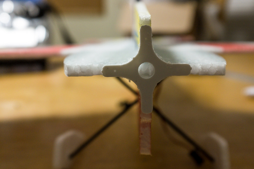
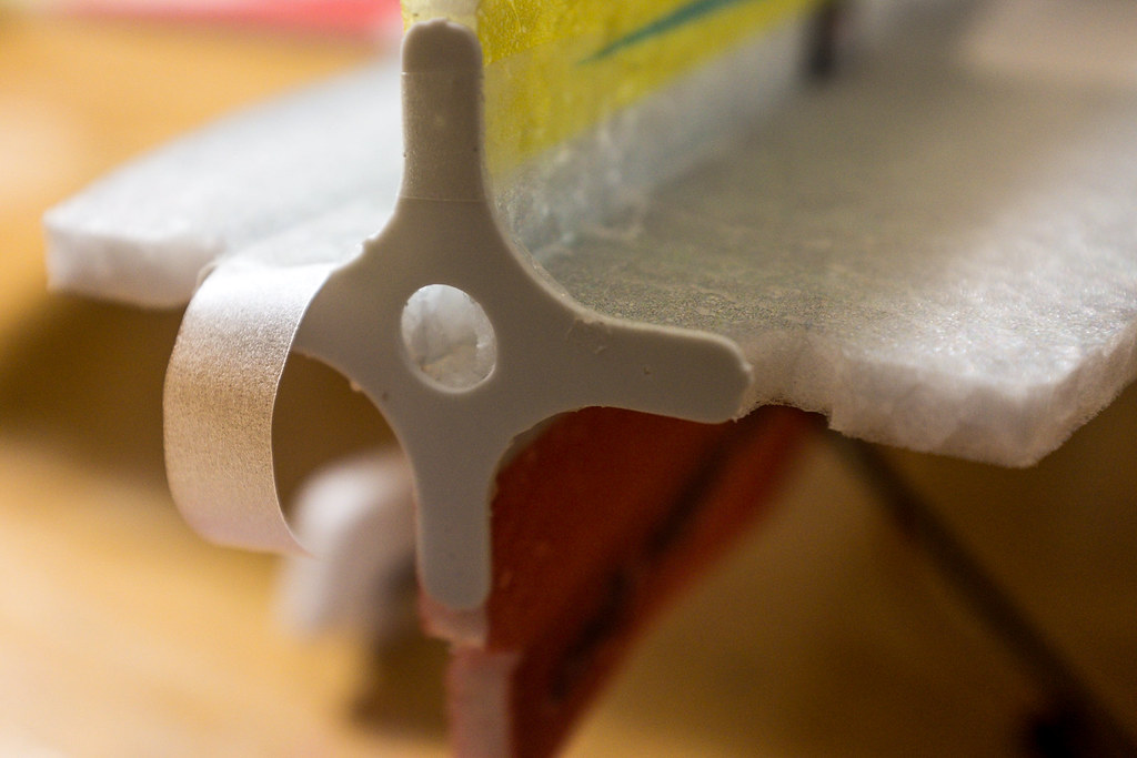
Install The Motor.
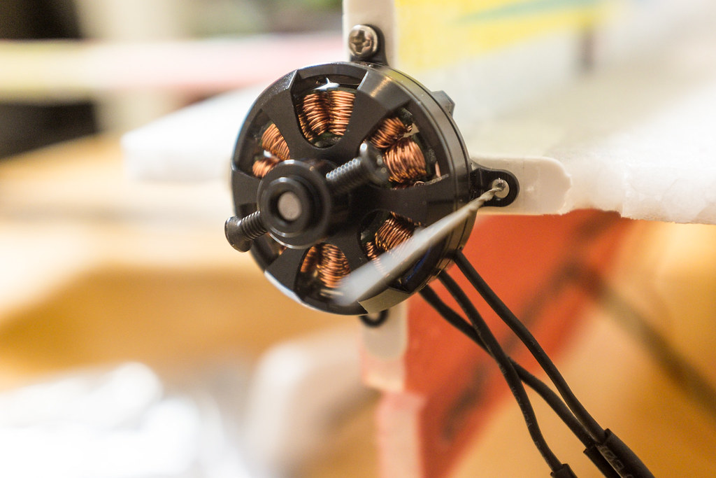
I use blenderm tape and a little welders to make a more rigid mount
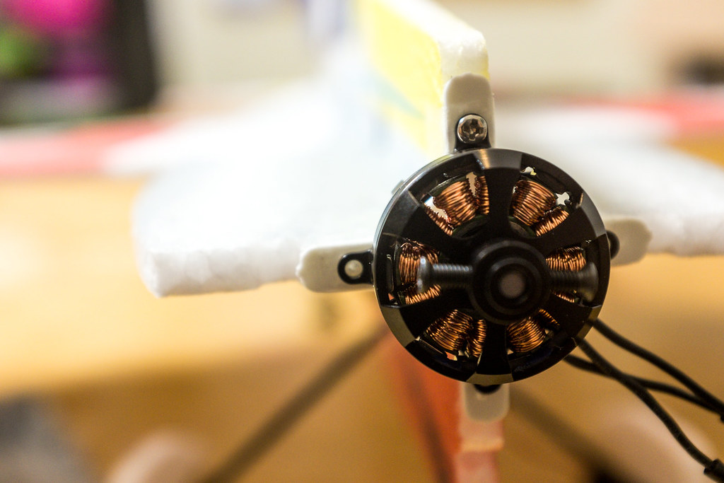
Next mount the motor.
Depending on how your motor hols are, you may have to drill some tiny holes to mount your motor (I mean tiny holes).
Setting up the Ailerons
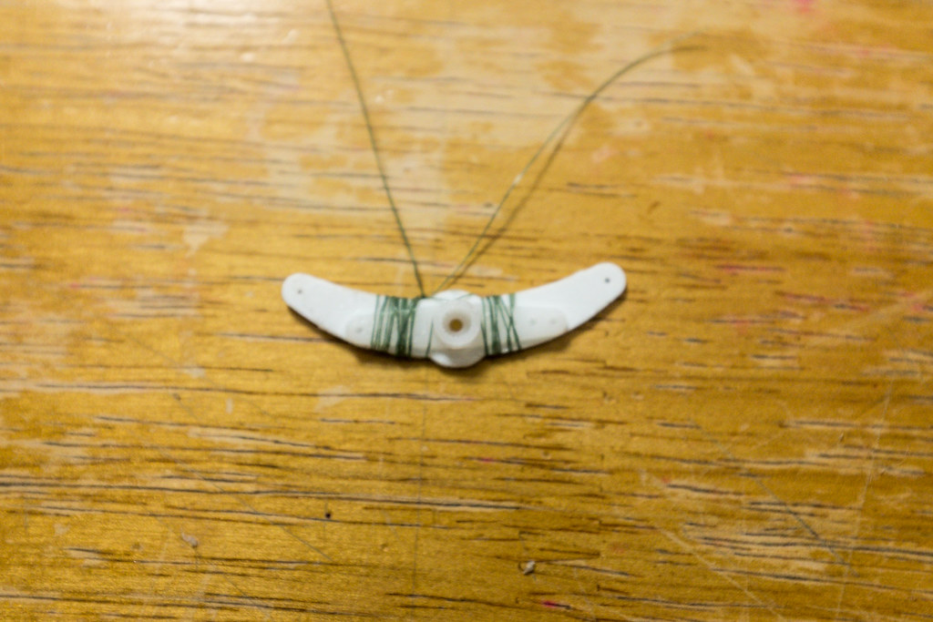
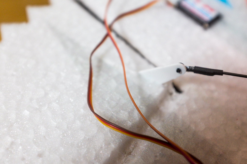
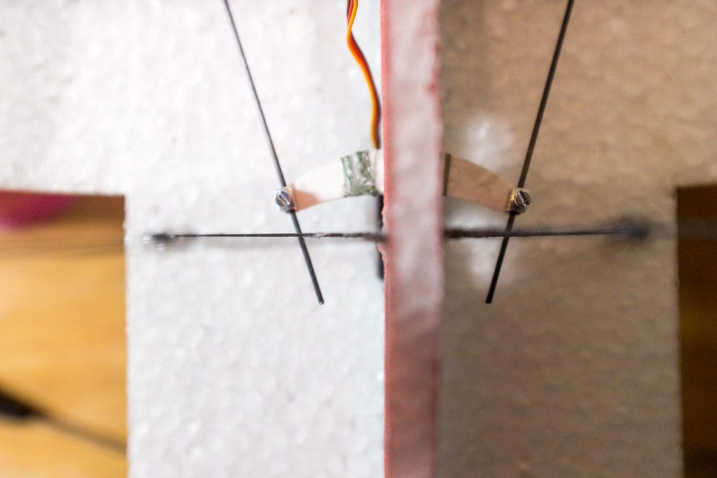
Make sure to set up your Aileron servo control arm (differential) so that the tips face forward like bull horns. Also dont be a dork like me (doh) and be sure pass the servo through the hole in the differential arm. Then use come CA and dental floss, (
SpyderWire is what I use) to wrap the diff arm tight to the servo arm.
