Aerobeez
70cc twin V2
Aerobeez 65" 20cc Extra 330sc Manual
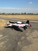
Hello 3DRC Forum, welcome to our official Step by Step build guide and manual for our Aerobeez 65" 20cc Extra 330sc. This manual will walk you through the steps to building our Extra. This Extra Profile will be built around the DLE-20 engine. Please take note that the build steps are that of our pilot Orel "Jazzy Hands" Elbaz. When building a profile ARF, there are several variations that can be taken. Such as your engine choice, side to mount your ignition/fuel tank. There is no real set method. Use your best judgment to see how the fuel tank and ignition placement will fit best for your engine configuration. Also with profile builds, the covering on the fuselage will need to be cut away in several areas to route wires, etc. Do not start cutting all the covering away at the same time. Cut the covering for the area you are working on then move on to the next step. We suggest doing this so that you do not cut away an area that was not needed to be cut. Now let's start the build!
Disclaimer: It is recommended that you read the instruction manual BEFORE beginning the build in order to get an idea of what is needed.
Needed for this build: #11 Hobby Knife, 20min epoxy, Thin CA, Medium CA, Acceton, and the Aerobeez 65" 20cc Extra 330sc
Setup: This plane is equipt with a DLE-20cc on a Xoar 16x8 propeller and we are running Hitec Hs-7954sh all around and a Hs-5665mh on throttle with a single 2550 2s Pulse Rx and Ignition pack. For this build we used our Miracle 1.5" servo arms.
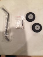
First we will begin by installing landing gear. Locate you carbon fiber landing gear, wheels, hardware bag, and wheel pants. (Note:In this picture I do not have wheel pants)
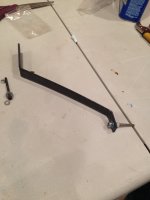
Next install your axle onto your landing gear. The order should be nut, washer, carbon fiber landing gear, wheel pant, white plastic washer, wheel, collar. (Note:REMEMBER TO USE LOCKTIGHT!)
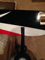
Next cut out the landing gear holes in fuse and install landing gear. Remember to locktight!
Tail wheel assembly is already installed so just screw into center of the tail. (Note: I recommend to remove all screws and apply locktight)
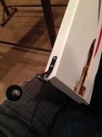
Next we will begin hinging the wings. Locate your ailerons, carbon fiber control horn and hinges.
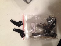
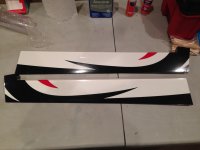
I recommend that you take some sand paper and scuff up both sides of the horn.
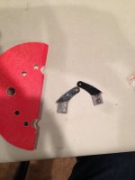
Now you will cut out the slot for the horn on the aileron
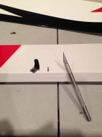
Now put some epoxy on the horn and in the slot (NOTE: CA can be used as well but I prefer epoxy)
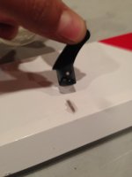
Now you can install you horn and wipe off the excess epoxy with paper towel. (Note: I like to wet the paper towel with Acetone, I have tried many things in the past but I found that nothing removes epoxy like Acetone)
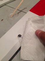
Next we will install our hinges. I like to prepare by rubbing the knuckles of the hinges with some Vasaline to keep the epoxy from sticking.
(NOTE: If this is your fist time I recommend using 20min Epoxy to give you time to make adjustments)
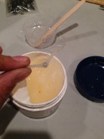
Now you can open up the holes on the wing and ailerons with a #11 blade.
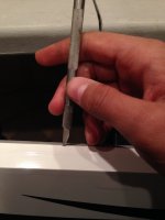
Then you can put some epoxy on your hinge and inside the holes and install your hinges to both surfaces and push together.
(NOTE: Use Acetone to clean the excess epoxy from the hinge line)
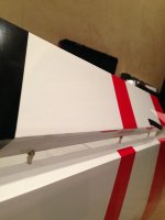
Now locate your wing brackets and install you your wing
(NOTE: Use locktight!)
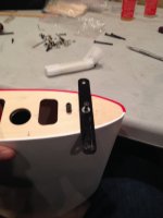
Use the same techniques to hinge the elevator.
(NOTE: Do NOT hinge the rudder yet!)
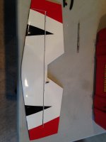
Next take a small handsaw or a razor blade and remove this part of the tail.
(NOTE: Do NOT throw this piece away, you will need it!)
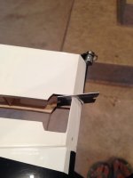
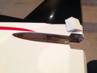
Now place your elevator in this slot and measure both sides to make sure it is centered and mark it with a pen.
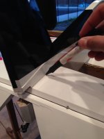
Using a sharp #11 blade remove the layer of Oracover reveling the wood on both sides.
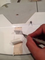
Now place the elevator back in the slot and glue with Thin CA on all sides then go over again with Medium CA.
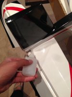
Now go ahead and install the piece of wood we cut out using some CA
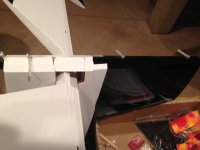
Now to add some extra security I decided to drill 1in under were the existing last hinge hole was and place the hinge in that new area.
(NOTE: This step is not mandatory but recommended)
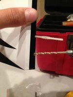
Now using the same steps as before hinge the rudder.
(NOTE: Do not install rudder horn yet)
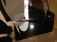
Now finish installing tail wheel.
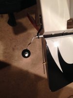
Next we can cut out these hole in the fuselage.
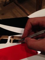
Cut out your desired tail servo location.
(NOTE: The rudder servo placement is under the elevator and the elevator servo location is in front of the elevator)
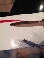
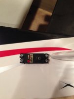
Now take a long pushrod and fish out your servo wires to the fuse holes we cut out.
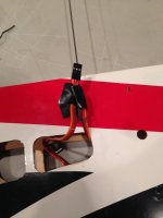
Now go ahead and cut out you aileron servo holes on the wing and install the servos.
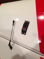
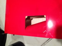
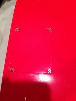
Now cut out your access holes on both wings and install doors with 4 wood screws supplied in kit.
Now you may install servo arms and push rods.
(NOTE: Don't forget to locktight pushrod screws)
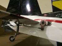
Now we can install your rudder servo horn. There is no rudder servo horn mount, it is mounted on the bottom of a stringer in your rudder.
(NOTE: Press rudder against stringer as it is drying to insure a tight strong bong. I recommend to use Epoxy for this)
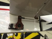
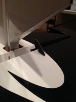
Now you may install your throttle servo.
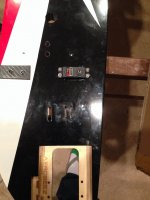
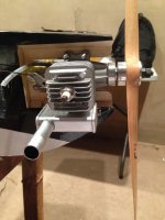
Next install your motor.
(VERY IMPORTANT NOTE: Use RED locktight when installing motor)
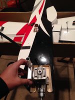
Now you may connect your throttle servo to you motor
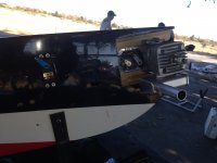
Next locate and install your fuel tank.
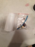
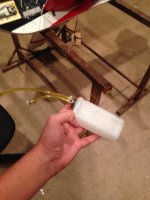
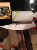
Now you can cut out the 4 little holes in the front of the plane using velcro and the zip-ties supplied in your kit mount your fuel tank.
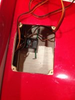
Now you can place your receiver in side the access panel on your wing and plug in all servos into your receiver.
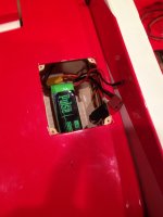
On the opposite side using strong velcro install your battery.
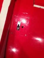
Cut out hole for your switch at the desired location.
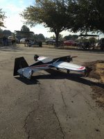
Now install propeller and ignition and you are ready to fly!

Thank You

Hello 3DRC Forum, welcome to our official Step by Step build guide and manual for our Aerobeez 65" 20cc Extra 330sc. This manual will walk you through the steps to building our Extra. This Extra Profile will be built around the DLE-20 engine. Please take note that the build steps are that of our pilot Orel "Jazzy Hands" Elbaz. When building a profile ARF, there are several variations that can be taken. Such as your engine choice, side to mount your ignition/fuel tank. There is no real set method. Use your best judgment to see how the fuel tank and ignition placement will fit best for your engine configuration. Also with profile builds, the covering on the fuselage will need to be cut away in several areas to route wires, etc. Do not start cutting all the covering away at the same time. Cut the covering for the area you are working on then move on to the next step. We suggest doing this so that you do not cut away an area that was not needed to be cut. Now let's start the build!
Disclaimer: It is recommended that you read the instruction manual BEFORE beginning the build in order to get an idea of what is needed.
Needed for this build: #11 Hobby Knife, 20min epoxy, Thin CA, Medium CA, Acceton, and the Aerobeez 65" 20cc Extra 330sc
Setup: This plane is equipt with a DLE-20cc on a Xoar 16x8 propeller and we are running Hitec Hs-7954sh all around and a Hs-5665mh on throttle with a single 2550 2s Pulse Rx and Ignition pack. For this build we used our Miracle 1.5" servo arms.
First we will begin by installing landing gear. Locate you carbon fiber landing gear, wheels, hardware bag, and wheel pants. (Note:In this picture I do not have wheel pants)

Next install your axle onto your landing gear. The order should be nut, washer, carbon fiber landing gear, wheel pant, white plastic washer, wheel, collar. (Note:REMEMBER TO USE LOCKTIGHT!)

Next cut out the landing gear holes in fuse and install landing gear. Remember to locktight!

Tail wheel assembly is already installed so just screw into center of the tail. (Note: I recommend to remove all screws and apply locktight)

Next we will begin hinging the wings. Locate your ailerons, carbon fiber control horn and hinges.


I recommend that you take some sand paper and scuff up both sides of the horn.

Now you will cut out the slot for the horn on the aileron

Now put some epoxy on the horn and in the slot (NOTE: CA can be used as well but I prefer epoxy)

Now you can install you horn and wipe off the excess epoxy with paper towel. (Note: I like to wet the paper towel with Acetone, I have tried many things in the past but I found that nothing removes epoxy like Acetone)

Next we will install our hinges. I like to prepare by rubbing the knuckles of the hinges with some Vasaline to keep the epoxy from sticking.
(NOTE: If this is your fist time I recommend using 20min Epoxy to give you time to make adjustments)

Now you can open up the holes on the wing and ailerons with a #11 blade.

Then you can put some epoxy on your hinge and inside the holes and install your hinges to both surfaces and push together.
(NOTE: Use Acetone to clean the excess epoxy from the hinge line)

Now locate your wing brackets and install you your wing
(NOTE: Use locktight!)

Use the same techniques to hinge the elevator.
(NOTE: Do NOT hinge the rudder yet!)

Next take a small handsaw or a razor blade and remove this part of the tail.
(NOTE: Do NOT throw this piece away, you will need it!)


Now place your elevator in this slot and measure both sides to make sure it is centered and mark it with a pen.

Using a sharp #11 blade remove the layer of Oracover reveling the wood on both sides.

Now place the elevator back in the slot and glue with Thin CA on all sides then go over again with Medium CA.

Now go ahead and install the piece of wood we cut out using some CA

Now to add some extra security I decided to drill 1in under were the existing last hinge hole was and place the hinge in that new area.
(NOTE: This step is not mandatory but recommended)

Now using the same steps as before hinge the rudder.
(NOTE: Do not install rudder horn yet)

Now finish installing tail wheel.

Next we can cut out these hole in the fuselage.

Cut out your desired tail servo location.
(NOTE: The rudder servo placement is under the elevator and the elevator servo location is in front of the elevator)


Now take a long pushrod and fish out your servo wires to the fuse holes we cut out.

Now go ahead and cut out you aileron servo holes on the wing and install the servos.

Now cut out your access holes on both wings and install doors with 4 wood screws supplied in kit.


Now you may install servo arms and push rods.
(NOTE: Don't forget to locktight pushrod screws)

Now we can install your rudder servo horn. There is no rudder servo horn mount, it is mounted on the bottom of a stringer in your rudder.
(NOTE: Press rudder against stringer as it is drying to insure a tight strong bong. I recommend to use Epoxy for this)


Now you may install your throttle servo.

Next install your motor.
(VERY IMPORTANT NOTE: Use RED locktight when installing motor)

Now you may connect your throttle servo to you motor

Next locate and install your fuel tank.


Now you can cut out the 4 little holes in the front of the plane using velcro and the zip-ties supplied in your kit mount your fuel tank.

Now you can place your receiver in side the access panel on your wing and plug in all servos into your receiver.

On the opposite side using strong velcro install your battery.

Cut out hole for your switch at the desired location.

Now install propeller and ignition and you are ready to fly!


Thank You
Last edited by a moderator:
