xCrashNBurnx
30cc
Zeus Power Box Intro

I first wanted to discuss why I wanted to take on this project. I outgrew my Hitec X4 AC Plus Multi-Charger and needed to upgrade to something with more power that would not only charge larger batteries but charge them faster. Most high-powered chargers require a separate, usually bulky power supply. Because I’m a bit OCD and can’t stand the thought of carrying a bunch of separate components to and from the field, I was compelled to build something better. Add to that the fact that once everything was connected at the field you usually end up with a rat nest of wires running everywhere. My goal was to put a high-powered system into a small case that would be easy to grab and head to the field. I wanted to design the box so that it would hide the unattractive power supplies and wiring and keep the chargers front and center for easy access. This is what I’ve come up with and I hope it helps people looking to do something similar.
Parts Listing
Before we move onto the build I wanted to give you a complete parts listing so I don't have to discuss each component throughout the build.
1 - Pelican Storm Case 2300
2 – FMA PowerLab 8 Chargers – http://www.epbuddy.com
1 – Solid Hobby 12v Power Supply with 575watts of power – http://www.solidhobby.com
1 – Solid Hobby 24v Power Supply with 1150watts of power – http://www.solidhobby.com
2 – 12v 90mm computer fans – http://www.Amazon.com
2 – 90mm fan grills – http://www.Amazon.com
1 – Powerwerx Chassis Mount for 2 Powerpoles – http://www.Powerwerx.com
1 – 12VDC Toggle Switch with Safety Cover – Radio Shack
1 – 12v Latching Push Button Switch – http://www.amazon.com
1 – 5v Digital LCD Thermometer - http://www.frozencpu.com
1 – 12v to 5v DC Converter - http://www.ebay.com
2 – 3ft Heavy Duty AD Power Cables - http://www.progressiverc.com/
2 – AC Case Adapter - http://www.progressiverc.com/
4 – Pelican Quick Mounts - http://www.pelican-case.com/15pelquicmou.html
3M Heavy Duty Velcro
Zip ties and zip tie mounts with adhesive backing
Step 1 - Planning, Measuring, Planning, Measuring
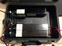
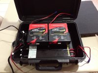
This is probably the most important step if you want to avoid items not fitting and then having to deal with returns and ordering new parts or equipment. You’ll see from some of the pictures that I didn’t take into consideration the location of the power supply switch. In order to rest the chargers on top of the power supplies, I had to relocate the switches which peeled away some of the black ultracoat, so I trimmed the covering up the best I could.
I’ve had this Pelican case for a while so I took the inside dimensions and did some quick mockups in a 3D modeling software that I know. However, this is not necessary and I suggest using cardboard prototypes or the actual parts to get a more accurate idea of how things will fit. I made cardboard prototypes of the power supplies and chargers based on the dimensions from the manufacturer’s website. Then I fit them into the case the way I wanted them laid out and made sure everything fit and the lid closed. Once I knew things were going to fit the way I wanted them to, I began ordering everything.
Step 2 – Customizing the Case
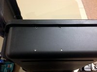
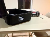
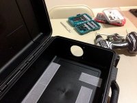
After I figured out the best location for both fans and optimal cooling, I drilled out the four mounting holes for each fan. I then drilled a large 80mm to 90mm hole for the intake and exhaust fans. To cut the large fan openings and AC adapter openings, I started with my Dremel and a cutting wheel. To fine tune the opening the best tool I found was the Dremel 432 ½†120 Grit Sanding Bands. At this time I also went ahead and cut the holes where I planned on mounting the AD power adapters. With the case empty, this is now a good time to install your heavy duty Velcro to use to Velcro in your power supplies. Trust me when I say that this velco will hold just about any size power supply or charger without any issues.
Step 3 – Installing the Power Supplies and Fans
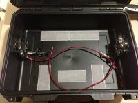
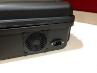
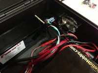
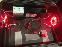
Once I figured out where I wanted to put both power supplies, I stuck soft Velcro to the inside, bottom of the case. I then stuck hard Velcro onto the bottom of each power supplies and installed them. Using screws, I then installed both fans and both outside fan grills. After that, I cut both power supply power chords to length. I then split and cut back the black coating to expose the individual positive, negative and ground wires. Then I stripped off about a quarter inch off each wire and crimped on standard QD connectors with protective shrouds. The only thing left to do was hook up the both power supplies to the AC adapters on the side of the case.
Step 4 – Installing the Fan Switch
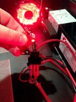
WARNING: This type of setup puts out a lot of power. If you’re not very experienced with wiring and electricity, I suggest that you take extreme caution during these next few steps. I have a basic knowledge of electricity, enough to accomplish most common electrical tasks around the home. However, because I was unsure on how to connect some of these switches and devices, I tested everything with a simple 9volt battery and alligator clips. Once I was sure I had everything working the way I wanted it to, I crimped on my connectors and started connecting everything up the power supplies. I used a 12v toggle switch with LED. This switch was pretty easy to install, in comparison to the push button latching switch. All you have to do is run the positive and negative wires from the power supply and both fans to the correct posts on the switch. There is a sticker on the side of the switch that tells you which wires connect to each post. I use smaller QD connectors with protective shrouds to connect the wires to the posts.
Step 5 – Installing the Digital Thermometer and Push Button LED Switch
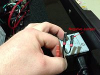
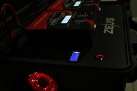
This is where the 9v battery came in handy. With pretty much no instructions or wiring diagram, this became a guessing game. There were some indicators on the back of the switch; + for positive, - for negative, NO for normally open and NC for normally closed. Normally open is how I wanted my switch to function, which means that the switch would be normally open and the thermometer would be off. However, there were 5 connections on the back and until I did some heavy Googling, I had no idea how to get the switch to work properly. I connected the positive from the thermometer and positive from the power supply to the positive of the switch. Then you connect the negative from the thermometer to the NO connection. The negative from the power supply get connecter to the blank center connector and then a jumper must be ran to the negative of the switch. This is how you must connect everything if you want the LED on the switch to turn on and off with the thermometer. Without the jumper the red LED on the switch was always on or always off.
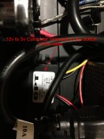
On a side note, be sure the read the ratings of all the components carefully so you don’t burn anything up. I burned up the first digital thermometer because even though it was built for computers, it wasn’t 12v it was actually a 5v thermometer. So if you’re going to use this type of thermometer you’ll need to run a 12v to 5v step down converter.

Step 6 – Designing the Charger Panel
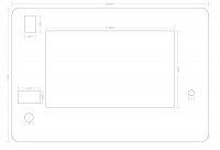
Besides having your entire charging system in one easy to carry case, the main reason I did this build was to hide all the ugly wires and components. I first downloaded the CAD file of the interior dimensions of my Pelican case from Pelican’s website. I then took the file into Adobe Illustrator and began laying out the location of all the switches and components that would be installed into the plate. Once I was satisfied with the layout, I printed the diagram to use as a template. I went to my local hobby store and purchased 2ft x 3ft piece of black foam core for 5 bucks, which would be enough for 2 prototypes. I then taped my template to the foam core and using an exacto knife, cut my prototype. I wanted to make sure everything actually fit before I had the final plate cut. If I made a small calculation error on the foam core, it would only cost me $2.50. The final plate, which was laser cut from a sheet of 1/8th inch thick stainless steel, cost $50.00. It was a good thing I did this too, because once the wires were connected to the bottoms of the switch, they were much taller than originally anticipated and I wasn’t able to recess them deep enough into the case because they were resting on some internal components. The latching push button switch for instance, even though it’s flush mounted on top, the bottom of the switch requires 2-3 inches of clearance bellow the panel. On my second prototype I had to tweak their location slightly so that the underside of the switches would clear the internal components below the panel. Once I had everything in the right location, I converted my template into a file that could be used with CAD. I then had my local machine shop laser cut my design out of 1/8th inch this stainless steel. You can also use a cool service I found online at frontpanelexpress.com. They have a free panel designing software that you can download. Once you’re finished with your design you can customize and order it your panel directly from the site. This is a pretty good alternative if you don’t have a laser CNC machine in your area. The final step in this process is what really made the charger panel look great! I wrapped it in 3M DI-NOC carbon fiber vinyl. This stuff not only looks like real carbon fiber, but the material was also pretty easy to work with.
Step 7 – Wire Management
Nothing to ground breaking here, but a necessary step if you want to make sure your case maintains maximum air flow. Also, if the wires aren’t securely fastened down they can move around during transport and could end up getting caught in the fans. To organize the wires, I use your average zip ties and zip tie mounts with adhesive backing. You can find the zip tie mounts on Amazon. I used the zip ties to basically bundle the wires but then zip tied the wires to the zip tie mounts to keep the wires from moving while transporting to and from the field.
Step 8 – Panel and Charger Installation
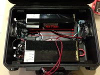
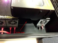
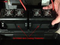
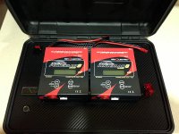
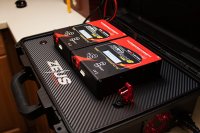
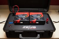
To create a level platform to mount the charger panel to I use 4 Pelican Quick Mounts. Each one attaches to the inside of the case via 2 screws. Start by deciding the depth you want the charger panel to sit and measure down the sides of the case to each mount to ensure that the plate will sit level. Make sure the screws you choose to mount the Quick Mounts with are not too long, so they don’t penetrate the outside of the case. I then put heavy duty velcro on top of the power supplies, on the bottom of the Power Lab 8s, on the top of the Quick Mounts and on the underside of the charger panel. After mounting the switches and thermometer into the panel all that’s left to do is hook up wires and set everything into place. Make sure you plan your case fitment and cooling. If you noticed, I had to partially recess the chargers to allow sufficient room for the lid to close. However, this ended up working out well because the cooling and intake vents of the charger line up directly with the overall air flow of the case.

Step 9 – Finishing Touches
Having worked in the advertising and design business for the last 14 years, I felt like the case needed some branding. So, I thought about what signifies serious power. The Greek God Zeus seemed like a pretty good fit so I designed my logo in Adobe Illustrator and sent the files to a friend of mine who owns a local sign company in town and he printed the logo on silver metallic vinyl. I post a video tomorrow, showing how easy this system is to power up and start charging.

I first wanted to discuss why I wanted to take on this project. I outgrew my Hitec X4 AC Plus Multi-Charger and needed to upgrade to something with more power that would not only charge larger batteries but charge them faster. Most high-powered chargers require a separate, usually bulky power supply. Because I’m a bit OCD and can’t stand the thought of carrying a bunch of separate components to and from the field, I was compelled to build something better. Add to that the fact that once everything was connected at the field you usually end up with a rat nest of wires running everywhere. My goal was to put a high-powered system into a small case that would be easy to grab and head to the field. I wanted to design the box so that it would hide the unattractive power supplies and wiring and keep the chargers front and center for easy access. This is what I’ve come up with and I hope it helps people looking to do something similar.
Parts Listing
Before we move onto the build I wanted to give you a complete parts listing so I don't have to discuss each component throughout the build.
1 - Pelican Storm Case 2300
2 – FMA PowerLab 8 Chargers – http://www.epbuddy.com
1 – Solid Hobby 12v Power Supply with 575watts of power – http://www.solidhobby.com
1 – Solid Hobby 24v Power Supply with 1150watts of power – http://www.solidhobby.com
2 – 12v 90mm computer fans – http://www.Amazon.com
2 – 90mm fan grills – http://www.Amazon.com
1 – Powerwerx Chassis Mount for 2 Powerpoles – http://www.Powerwerx.com
1 – 12VDC Toggle Switch with Safety Cover – Radio Shack
1 – 12v Latching Push Button Switch – http://www.amazon.com
1 – 5v Digital LCD Thermometer - http://www.frozencpu.com
1 – 12v to 5v DC Converter - http://www.ebay.com
2 – 3ft Heavy Duty AD Power Cables - http://www.progressiverc.com/
2 – AC Case Adapter - http://www.progressiverc.com/
4 – Pelican Quick Mounts - http://www.pelican-case.com/15pelquicmou.html
3M Heavy Duty Velcro
Zip ties and zip tie mounts with adhesive backing
Step 1 - Planning, Measuring, Planning, Measuring
This is probably the most important step if you want to avoid items not fitting and then having to deal with returns and ordering new parts or equipment. You’ll see from some of the pictures that I didn’t take into consideration the location of the power supply switch. In order to rest the chargers on top of the power supplies, I had to relocate the switches which peeled away some of the black ultracoat, so I trimmed the covering up the best I could.
I’ve had this Pelican case for a while so I took the inside dimensions and did some quick mockups in a 3D modeling software that I know. However, this is not necessary and I suggest using cardboard prototypes or the actual parts to get a more accurate idea of how things will fit. I made cardboard prototypes of the power supplies and chargers based on the dimensions from the manufacturer’s website. Then I fit them into the case the way I wanted them laid out and made sure everything fit and the lid closed. Once I knew things were going to fit the way I wanted them to, I began ordering everything.


Step 2 – Customizing the Case
After I figured out the best location for both fans and optimal cooling, I drilled out the four mounting holes for each fan. I then drilled a large 80mm to 90mm hole for the intake and exhaust fans. To cut the large fan openings and AC adapter openings, I started with my Dremel and a cutting wheel. To fine tune the opening the best tool I found was the Dremel 432 ½†120 Grit Sanding Bands. At this time I also went ahead and cut the holes where I planned on mounting the AD power adapters. With the case empty, this is now a good time to install your heavy duty Velcro to use to Velcro in your power supplies. Trust me when I say that this velco will hold just about any size power supply or charger without any issues.


Step 3 – Installing the Power Supplies and Fans
Once I figured out where I wanted to put both power supplies, I stuck soft Velcro to the inside, bottom of the case. I then stuck hard Velcro onto the bottom of each power supplies and installed them. Using screws, I then installed both fans and both outside fan grills. After that, I cut both power supply power chords to length. I then split and cut back the black coating to expose the individual positive, negative and ground wires. Then I stripped off about a quarter inch off each wire and crimped on standard QD connectors with protective shrouds. The only thing left to do was hook up the both power supplies to the AC adapters on the side of the case.


Step 4 – Installing the Fan Switch
WARNING: This type of setup puts out a lot of power. If you’re not very experienced with wiring and electricity, I suggest that you take extreme caution during these next few steps. I have a basic knowledge of electricity, enough to accomplish most common electrical tasks around the home. However, because I was unsure on how to connect some of these switches and devices, I tested everything with a simple 9volt battery and alligator clips. Once I was sure I had everything working the way I wanted it to, I crimped on my connectors and started connecting everything up the power supplies. I used a 12v toggle switch with LED. This switch was pretty easy to install, in comparison to the push button latching switch. All you have to do is run the positive and negative wires from the power supply and both fans to the correct posts on the switch. There is a sticker on the side of the switch that tells you which wires connect to each post. I use smaller QD connectors with protective shrouds to connect the wires to the posts.


Step 5 – Installing the Digital Thermometer and Push Button LED Switch
This is where the 9v battery came in handy. With pretty much no instructions or wiring diagram, this became a guessing game. There were some indicators on the back of the switch; + for positive, - for negative, NO for normally open and NC for normally closed. Normally open is how I wanted my switch to function, which means that the switch would be normally open and the thermometer would be off. However, there were 5 connections on the back and until I did some heavy Googling, I had no idea how to get the switch to work properly. I connected the positive from the thermometer and positive from the power supply to the positive of the switch. Then you connect the negative from the thermometer to the NO connection. The negative from the power supply get connecter to the blank center connector and then a jumper must be ran to the negative of the switch. This is how you must connect everything if you want the LED on the switch to turn on and off with the thermometer. Without the jumper the red LED on the switch was always on or always off.
On a side note, be sure the read the ratings of all the components carefully so you don’t burn anything up. I burned up the first digital thermometer because even though it was built for computers, it wasn’t 12v it was actually a 5v thermometer. So if you’re going to use this type of thermometer you’ll need to run a 12v to 5v step down converter.


Step 6 – Designing the Charger Panel
Besides having your entire charging system in one easy to carry case, the main reason I did this build was to hide all the ugly wires and components. I first downloaded the CAD file of the interior dimensions of my Pelican case from Pelican’s website. I then took the file into Adobe Illustrator and began laying out the location of all the switches and components that would be installed into the plate. Once I was satisfied with the layout, I printed the diagram to use as a template. I went to my local hobby store and purchased 2ft x 3ft piece of black foam core for 5 bucks, which would be enough for 2 prototypes. I then taped my template to the foam core and using an exacto knife, cut my prototype. I wanted to make sure everything actually fit before I had the final plate cut. If I made a small calculation error on the foam core, it would only cost me $2.50. The final plate, which was laser cut from a sheet of 1/8th inch thick stainless steel, cost $50.00. It was a good thing I did this too, because once the wires were connected to the bottoms of the switch, they were much taller than originally anticipated and I wasn’t able to recess them deep enough into the case because they were resting on some internal components. The latching push button switch for instance, even though it’s flush mounted on top, the bottom of the switch requires 2-3 inches of clearance bellow the panel. On my second prototype I had to tweak their location slightly so that the underside of the switches would clear the internal components below the panel. Once I had everything in the right location, I converted my template into a file that could be used with CAD. I then had my local machine shop laser cut my design out of 1/8th inch this stainless steel. You can also use a cool service I found online at frontpanelexpress.com. They have a free panel designing software that you can download. Once you’re finished with your design you can customize and order it your panel directly from the site. This is a pretty good alternative if you don’t have a laser CNC machine in your area. The final step in this process is what really made the charger panel look great! I wrapped it in 3M DI-NOC carbon fiber vinyl. This stuff not only looks like real carbon fiber, but the material was also pretty easy to work with.

Step 7 – Wire Management
Nothing to ground breaking here, but a necessary step if you want to make sure your case maintains maximum air flow. Also, if the wires aren’t securely fastened down they can move around during transport and could end up getting caught in the fans. To organize the wires, I use your average zip ties and zip tie mounts with adhesive backing. You can find the zip tie mounts on Amazon. I used the zip ties to basically bundle the wires but then zip tied the wires to the zip tie mounts to keep the wires from moving while transporting to and from the field.
Step 8 – Panel and Charger Installation
To create a level platform to mount the charger panel to I use 4 Pelican Quick Mounts. Each one attaches to the inside of the case via 2 screws. Start by deciding the depth you want the charger panel to sit and measure down the sides of the case to each mount to ensure that the plate will sit level. Make sure the screws you choose to mount the Quick Mounts with are not too long, so they don’t penetrate the outside of the case. I then put heavy duty velcro on top of the power supplies, on the bottom of the Power Lab 8s, on the top of the Quick Mounts and on the underside of the charger panel. After mounting the switches and thermometer into the panel all that’s left to do is hook up wires and set everything into place. Make sure you plan your case fitment and cooling. If you noticed, I had to partially recess the chargers to allow sufficient room for the lid to close. However, this ended up working out well because the cooling and intake vents of the charger line up directly with the overall air flow of the case.


Step 9 – Finishing Touches
Having worked in the advertising and design business for the last 14 years, I felt like the case needed some branding. So, I thought about what signifies serious power. The Greek God Zeus seemed like a pretty good fit so I designed my logo in Adobe Illustrator and sent the files to a friend of mine who owns a local sign company in town and he printed the logo on silver metallic vinyl. I post a video tomorrow, showing how easy this system is to power up and start charging.


