Bartman
Defender of the Noob!
By now everyone probably knows I have a really nice BME 102 that I've been trying to sell in the classifieds. Someone questioned the ignition caps that were on the engine and when I couldn't verify the integrity of the caps (it was mid winter and I wasn't going to bench run the engine outside in the snow and cold) I opted to just send the dual ignition unit to CH Ignitions so they could verify the unit works and replace the ignition wires and caps.
As it turned out, I never mentioned that the engine has CH-6 spark plugs and Adrian from CH never asked so he put ignition caps on that were too big. When I saw him at Toledo a couple of weeks ago he offered me two ch-6 plug caps and sat me down to show me how to install them.
Before we get to the photos I'd just like to explain ignition wires briefly as there are a lot of different styles of wires and caps out there.
Spark plug caps can be anything from a bare clip that snaps onto the top of the spark plug to a full metal shroud that slides over the spark plug and is held firmly in place by a steel ring/spring. Whatever you have there needs to be a path to the plug for electricity and a path back to ground to complete the circuit. There will always be two wires regardless of the kind of ignition system you have.
The tip of the spark plug is the positive pole and the base of the spark plug (and the rest of the engine case actually) is the negative pole. The electricity travels down through the center of the spark plug and then jumps across the gap at the base of the plug to the bent metal piece to create a spark which makes the engine run.
Magneto systems will usually have one wire to the plug (positive or hot) and then another wire (ground) from the case back to the coil. Since you can't turn off a magneto there needs to be a way to prevent the magneto from sending a spark to the spark plug when you don't want it to. So you will sometimes find a switch in the ground wire to break the circuit thus preventing the plug from sparking. Magnetos can also be disabled by grounding the hot wire directly to the case (someone correct me if I'm wrong about that) so that the electricity meant to create a spark will instead be grounded into the case when the system is switched off.
Electronic ignition systems will also have two wires but they will be more likely to go directly to the top of the spark plug and then directly back to the ignition unit from the base of the spark plug via a full metal ignition cap. The BME engine that I have had rubber spark plug caps with metal clips inside to snap onto the tops of the plugs and the exterior wire of the spark plug wires were supposed to be the ground wires attached to the engine case via a lug on the case.
Electronic ignition systems will run so long as they are powered via an onboard battery and so they also need a switch of some sort so they can be shut off. "Optical Kill Switches" are a radio controlled switch and are commonly used to enable electronic ignition systems to be turned off when the receiver is not powered or via a switch on your transmitter. It is never recommended to attach a battery directly to your gas engine's ignition system when going flying.
When CH rehabbed my ignition unit Adrian put new wires and full metal caps on so the external ground wires and engine lugs were no longer necessary. He also replaced the old stiff wires with newer more flexible wires.
Here are the photos from the Toledo Weak Signals RC Expo showing how the new caps are installed.
First, a pic of Adrian from CH Ignitions. He was very helpful!

Now, to begin you have to prepare your wires by sliding on the heat shrink tubing that will seal everything up later
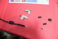
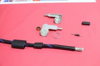
Next, slide the metal crimp sleeve onto the wire. This will later be used to anchor the ground wire onto the metal case of the ignition cap and hold the two halves of the case together.
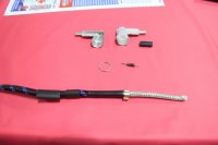
Next push the outer wire weave back away from the end of the wire. This weave is the return path or ground wire for the ignition circuit
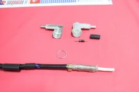
A resistor is part of the circuit (probably to shape or condition the spark to pop just right if I had to guess) and so the resistor gets shoved into the end of the wire so that it is tight against the inner wire
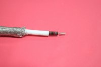
Heat shrink tubing is put over the resistor so that it is flush with the end of the resistor and then a heat gun is used to shrink the tubing into place
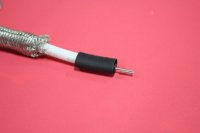
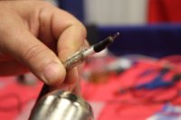
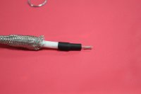
Adrian recommends using a pair of needle nose pliers to stretch the inner rubber insulator before pushing the wire into it...the bent end of the resistor should be visible looking into the insulator
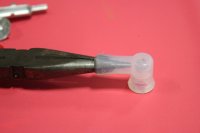
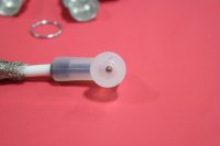
Next put the two halves of the metal ignition cap into place and slide the metal wire weave over the end of the cap. With the metal weave in place slide the metal crimping sleeve up over the wire so that it is also over the end of the two ignition cap halves.
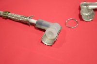
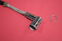
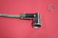
Slide the metal crimping sleeve over the metal braid and use a pair of diagonal cutters or flush cutters to crimp the two ears of the crimping sleeve. Do not squeeze so hard that the crimping sleeve will be damaged by the sharp jaws of the cutters. If you've squeezed hard enough then the wire weave will be held tightly in place by the crimping sleeve.
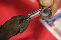
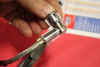
Once the sleeve is crimped into place, use a pair of pliers to fold over the small metal tabs that will hold the rest of the ignition cap together. Make sure you get them all, there are probably four or five of them.
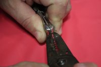
Now slide a short piece of heat shrink tubing over the crimping sleeve to seal it up and insulate the wires
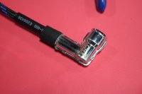
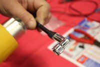
Slide the longer piece into place over the body of the ignition cap and use a heat gun to get everything nice and tight
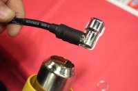
The last step is to slide the wire ring into place over the open end of the ignition cap so that the cap will snap into place and not come loose during flight. Adrian removed/snipped a small section of the ring to help it go on more easily.
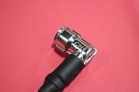
If you've done it correctly (it wasn't hard!) you'll have very secure connections for your wires and a cap that will stay tightly attached to your spark plug for a long time to come!
As it turned out, I never mentioned that the engine has CH-6 spark plugs and Adrian from CH never asked so he put ignition caps on that were too big. When I saw him at Toledo a couple of weeks ago he offered me two ch-6 plug caps and sat me down to show me how to install them.
Before we get to the photos I'd just like to explain ignition wires briefly as there are a lot of different styles of wires and caps out there.
Spark plug caps can be anything from a bare clip that snaps onto the top of the spark plug to a full metal shroud that slides over the spark plug and is held firmly in place by a steel ring/spring. Whatever you have there needs to be a path to the plug for electricity and a path back to ground to complete the circuit. There will always be two wires regardless of the kind of ignition system you have.
The tip of the spark plug is the positive pole and the base of the spark plug (and the rest of the engine case actually) is the negative pole. The electricity travels down through the center of the spark plug and then jumps across the gap at the base of the plug to the bent metal piece to create a spark which makes the engine run.
Magneto systems will usually have one wire to the plug (positive or hot) and then another wire (ground) from the case back to the coil. Since you can't turn off a magneto there needs to be a way to prevent the magneto from sending a spark to the spark plug when you don't want it to. So you will sometimes find a switch in the ground wire to break the circuit thus preventing the plug from sparking. Magnetos can also be disabled by grounding the hot wire directly to the case (someone correct me if I'm wrong about that) so that the electricity meant to create a spark will instead be grounded into the case when the system is switched off.
Electronic ignition systems will also have two wires but they will be more likely to go directly to the top of the spark plug and then directly back to the ignition unit from the base of the spark plug via a full metal ignition cap. The BME engine that I have had rubber spark plug caps with metal clips inside to snap onto the tops of the plugs and the exterior wire of the spark plug wires were supposed to be the ground wires attached to the engine case via a lug on the case.
Electronic ignition systems will run so long as they are powered via an onboard battery and so they also need a switch of some sort so they can be shut off. "Optical Kill Switches" are a radio controlled switch and are commonly used to enable electronic ignition systems to be turned off when the receiver is not powered or via a switch on your transmitter. It is never recommended to attach a battery directly to your gas engine's ignition system when going flying.
When CH rehabbed my ignition unit Adrian put new wires and full metal caps on so the external ground wires and engine lugs were no longer necessary. He also replaced the old stiff wires with newer more flexible wires.
Here are the photos from the Toledo Weak Signals RC Expo showing how the new caps are installed.
First, a pic of Adrian from CH Ignitions. He was very helpful!
Now, to begin you have to prepare your wires by sliding on the heat shrink tubing that will seal everything up later


Next, slide the metal crimp sleeve onto the wire. This will later be used to anchor the ground wire onto the metal case of the ignition cap and hold the two halves of the case together.

Next push the outer wire weave back away from the end of the wire. This weave is the return path or ground wire for the ignition circuit

A resistor is part of the circuit (probably to shape or condition the spark to pop just right if I had to guess) and so the resistor gets shoved into the end of the wire so that it is tight against the inner wire

Heat shrink tubing is put over the resistor so that it is flush with the end of the resistor and then a heat gun is used to shrink the tubing into place


Adrian recommends using a pair of needle nose pliers to stretch the inner rubber insulator before pushing the wire into it...the bent end of the resistor should be visible looking into the insulator


Next put the two halves of the metal ignition cap into place and slide the metal wire weave over the end of the cap. With the metal weave in place slide the metal crimping sleeve up over the wire so that it is also over the end of the two ignition cap halves.


Slide the metal crimping sleeve over the metal braid and use a pair of diagonal cutters or flush cutters to crimp the two ears of the crimping sleeve. Do not squeeze so hard that the crimping sleeve will be damaged by the sharp jaws of the cutters. If you've squeezed hard enough then the wire weave will be held tightly in place by the crimping sleeve.


Once the sleeve is crimped into place, use a pair of pliers to fold over the small metal tabs that will hold the rest of the ignition cap together. Make sure you get them all, there are probably four or five of them.

Now slide a short piece of heat shrink tubing over the crimping sleeve to seal it up and insulate the wires


Slide the longer piece into place over the body of the ignition cap and use a heat gun to get everything nice and tight

The last step is to slide the wire ring into place over the open end of the ignition cap so that the cap will snap into place and not come loose during flight. Adrian removed/snipped a small section of the ring to help it go on more easily.

If you've done it correctly (it wasn't hard!) you'll have very secure connections for your wires and a cap that will stay tightly attached to your spark plug for a long time to come!
Last edited:


