cwojcik
70cc twin V2
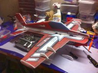
Hey guys, I thought I would post a little build of the new Crack Laser. I'm extremely proud of this airplane, and I think you will all love it! In this build I will incorporate some new durability tips we have learned with these airplanes, which are applicable to any EPP foamy. I will also post a separate article on these new techniques.
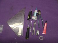
First, lay out your tools and supplies...a square, Phillips and flat-head screwdrivers, tweezers, CA, the ubiquitous Welder glue, hobby knife with fresh blades, wire cutters, and new for this build: Blenderm tape. Also recommended but not shown is a good set of weights and some parchment paper.
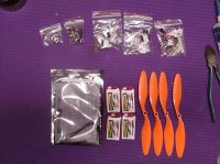
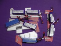
Also pictured is the Twisted Lite Power Combo including 1750 KV motor, 6 amp ESC, 8x4.3 GWS props, 2X CS-40D and 1X CS-90D servos. Also some 360 mah batteries.
Fuselage parts
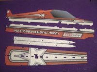
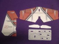
Wing parts
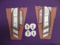
Tail parts, small foam parts, wheelpants
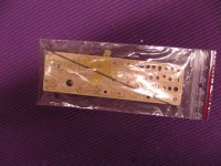
Hardware pack
The very first thing you should do is fold each hinge back 180 degrees and put a weight on it for a few hours or overnight. This will make the hinges more supple and really help take load off of the servos.
Next let's reinforce the hinges. First cut a small piece of Blenderm tape.
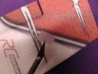
Put a small bead of glue near the end of the hinge line.
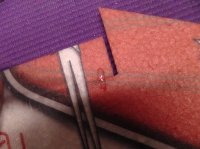
Lay the piece of tape on the glue, sticky side down.
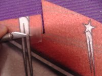
Flatten it and press the glue out to the edges of the tape.
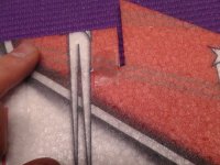
You can use your knife like a rolling pin to get it perfectly flat.
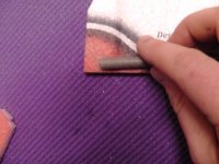
The result is an almost invisible reinforcement that won't break. Do this at the ends of the elevator and rudder, and the root and tip of the aileron. There is no need to do it near the inboard counterbalance.
Now let's assemble the wings and horizontal fuselage. Lay out a piece of parchment paper (note: this should really be the same size as the wings).
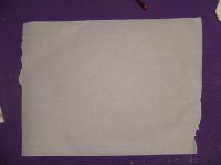
Test fit the wings together and make sure everything lines up. We will do this assembly upside-down.
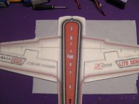
Lay a bead of Welder glue on the mating surface the wing...
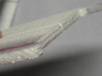
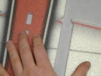
....press it together to wet both surfaces....
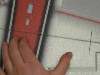
...then pull it apart and let it tack up.
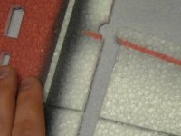
After the glue is tacky but not wet, press the wings together. It will grab tightly.
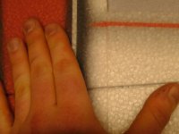
Cut out the 4 ribs.
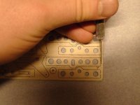
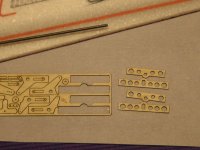
Find the spars...they are the long carbon tubes.
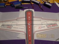
Clean out the slots for the spars with a sharp knife.
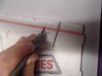
This is how the spars go in...the short spar goes in first, the longer spar is on top. The bumps on the ribs point out of the bottom of the wing.
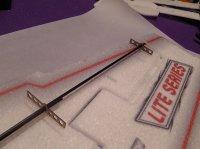
Test fit the spars and ribs in to make sure everything fits well.
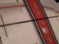
Spread some glue in the slots for the spars and ribs.
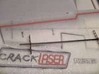
...and then install the spars and ribs. Wipe up any glue that squirts out.
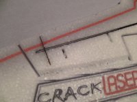
Weight down the assembly and let it dry completely.
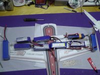
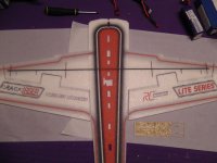
Now let's do some optional reinforcement. Lay a bead of glue down across where the wing meets the fuselage...do this in four places: the trailing edge and the leading edge, on both sides.
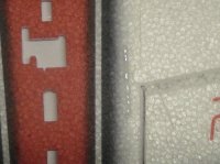
Now lay a piece of blenderm over these strips of glue. Press it down just like you did with the hinges.
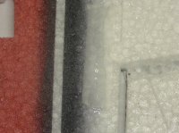
After you repeat this on all four corners, you will have a much stronger fuselage. I find that these models tear here a lot but this really prevents that.
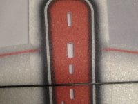
Glue the stab and elevator on the fuselage with the same procedure as the wings.
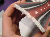
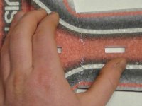
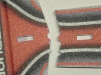
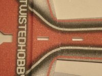
Add a fillet of glue at the corner of the stab and fuselage. This will help with durability.
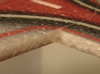
Now it's time to install some servos. Plug in all of your electronics and test them.
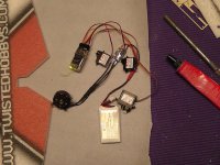
Here's a trick we have found...spread some glue thinly in the servo cutout and LET IT DRY COMPLETELY.
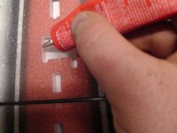
Do the same on all mating surfaces of the servos, letting them dry completely. When you install them, you can pop them in and they will not move around at all. However they will be much easier to remove than if you had glued them in normally.
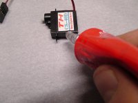
Now let's install the aileron horns. Cut them out of the plywood piece and cut the pushrod guides out of the horns.
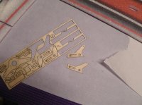
Store the pushrod guides in the hardware bag...they are easy to lose.
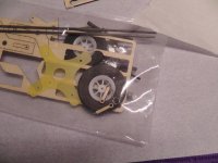
Clean out the slots for the aileron horns on the ailerons.
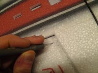
Install the EZ connectors on the aileron horns.
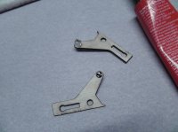
Make sure the screw hole is point out, away from the fuselage, so you can get to it with a screwdriver.
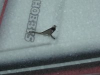
Now pop in the aileron servo. You may need to gently pull the foam away to work it in there but it will go in.
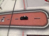
Do the same for the rudder servo.
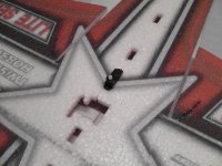
Power up the rudder servo to center it, then install the arm. You should also install the EZ-connector on the arm before you install it (not shown here).
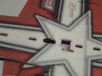
Test fit the upper fuse half on the wing and horizontal fuse to make sure everything clears properly.
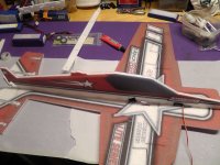
You will likely have to cut a small clearance for the aileron servo wire.
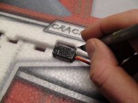
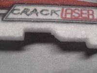
Spread some glue on the mating surface of the upper fuse half.
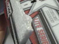
Install the upper fuse half...
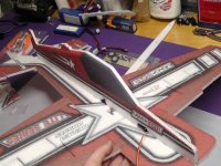
...and make sure it is lined up correctly.
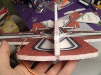
Once the upper fuse half has dried a bit, hang it off of the edge of your bench.
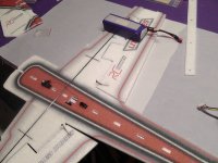
We can now install the elevator servo. Make sure it is centered, and install the arm and EZ connector. Pop it into the fuselage.
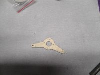
We can now also the aileron arm. Cut it out of the wood parts.
Find the round servo wheel for the aileron servo. The hub fits neatly in the hole of the arm.
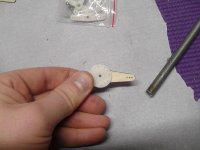
Add a little Welder glue to the surface of the round servo wheel and glue it onto the aileron arm. DO NOT LET IT DRY YET.
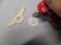
Before the glue dries, center the aileron servo, and install the arm. Now, with the glue still wet, rotate the aileron arm until it's perfectly aligned. Now you can get full travel and perfect centering without using sub-trim. Install the screw (not shown).
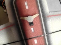
Weight down the wing and install the lower fuselage half. Test fit it with no glue to make sure everything clears.
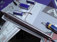
Then glue it on, and use your square to make sure it's all lined up.
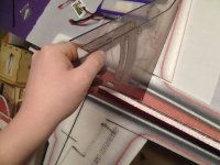
Check the alignment at both ends.
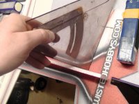
Next, let's install the foam braces that keep the tail torsionally stiff.
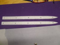
Trim the front of one of the braces off to clear the servo wires. Hang on to this piece.
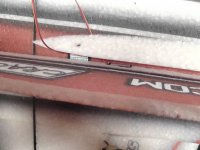
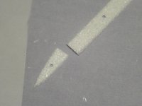
Glue them on carefully, keeping everything aligned.
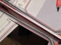
Next let's glue on the motor mount. Wet it with plenty of Welder glue....I have found there is no need to scuff it.
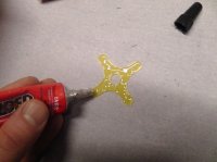
And stick it on the front of the airplane, lining everything up carefully.
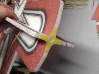
Let it dry a bit. Now, time for another new reinforcement tip...first, smear some Welder glue all around the area behind the motor mount legs.
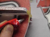
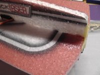
Cut some blenderm strips maybe 2.5" long, and carefully wrap them around the motor mount and over the glue you just applied.
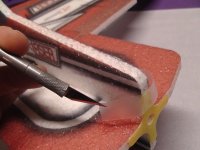
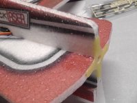
Repeat on all legs of the motormount. This will keep the front of the plane from tearing off in a really hard crash.
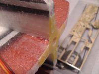
Open up the holes for the motor mount screws with your knife.
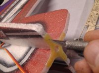
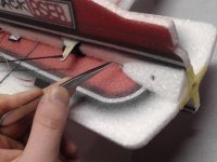
Finally, find the piece of the foam tail brace you cut off for wire clearance, and glue it on at the front of the airplane. This will keep the nose stiff and add some reinforcement.
Next let's assemble the landing gear. Get the plywood hockey-stick shaped pieces out of the hardware set, the T-shaped wheelpant mounts, as well as the short carbon axles, wheels, and flat gear legs.
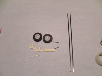
Drill out the axles with a 1/16" bit.
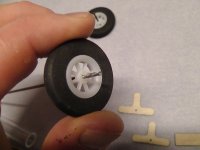
Glue the wood part to the gear leg with a drop of medium or thin CA.
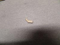
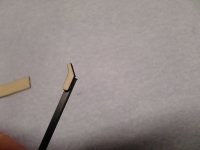
Glue the axle to the other end of the wood part, repeat for the other leg.
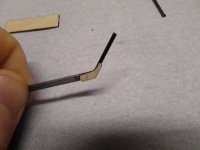
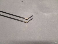
Now wrap the wood part and joints with thread. Anything will work; here I am using carbon tow but sewing thread is fine too. After it is wrapped add a drop of thin CA to the thread.
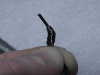
Next slip the wheel onto the axle as well as the T-shaped wheelpant mount. Put a drop of CA on the joint for the wheelpant mount to secure it.
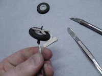
Put the gear legs aside while we install the aileron pushrods...it will be easier this way.
Find the stiff, round rods from the hardware pack, as well as two Z-bent wires, and two pieces of heatshrink tubing. Scuff up the wire with some sandpaper to promote good adhesion.
Put a Z-bent wire on the end of each pushrod with heatshrink.
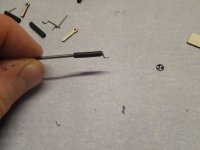
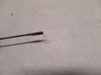
Add a drop of thin CA where the wire protrudes from the heatshrink. It will wick into the joint and cure.
Next put each pushrod in the aileron arm, and then flex the ailerons to insert the other end of the pushrod into the EZ connector. With everything centered, tighten the screws, and trim off the excess pushrod, leaving about 1/4" extra.
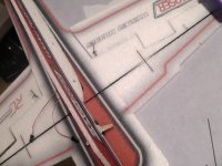
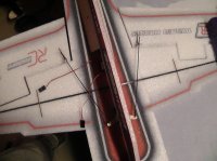
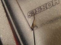
With the gear legs prepared, let's install them on the fuselage. Find the plywood rectangle for the wood parts. There is a cutout on the lower fuse where the gear legs pass through; the rectangle goes between the gear legs at this point. Clean it out with your knife.
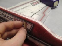
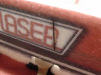
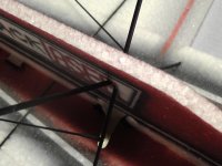
After dry-fitting everything, pull it all out a bit, add some glue, and reassemble. Make a good fillet where the ends of the gear legs engage the fuselage (there are holes there).
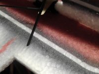
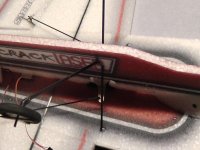
Now is a good time to install the elevator and rudder horns. These are different than the aileron horns but identical to each other. Pop them out of the hardware package and cut the pushrod guides out of them.
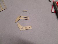
Clean out the slots that are cut for the horns in the surfaces with your knife.
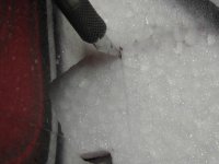
Finally, glue the horns in with some Welder glue.
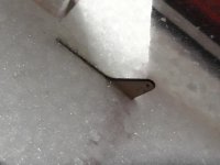
Next we can do the elevator and rudder pushrods. These are the long carbon rods from your carbon pack. Attach the Z-bends to the rods with heatshrink and CA just like you did with the aileron pushrods, then thread on six of the plywood pushrod guides on each pushrod. Then, insert the Z-bend end into the horn, and push the other end of the pushrod into the EZ-connector on the servo.
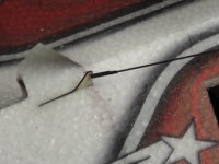
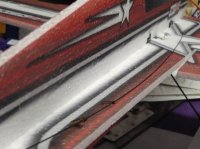
Next, carefully find the lasercut holes for the pushrod guides, and carefully glue them into the holes, being sure not to get any glue on the pushrod. You can use either Welder glue or CA here.
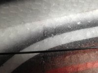
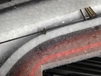
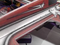
Now trim off the excess pushrod length and insert it into the bottom of the fuse to make a tailskid.
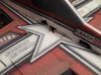
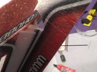
Finally, it's a good time now to install the SFG's and T-canalizer. The wing SFG's need to be split before they can be glued on...take care to make sure everything is properly lined up.
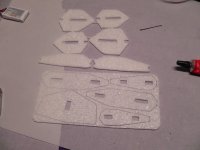
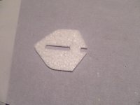
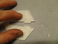
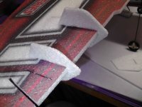
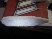
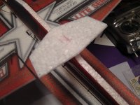
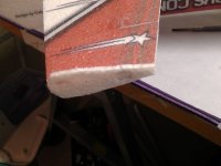
Finally, cut a hole in the wheelpants for the axle and glue them on.
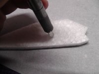
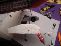
Alright, almost there!
Let's prepare the motor for mounting. First, another new tip for longevity: I have often found that after quite a few hard hits, it's not uncommon for motor wires to break. Often this happens just inside the motor and it means that motor is toast.
You can prevent this by adding some Welder glue to the wires where they exit the motor. This fillet of glue will protect the wires and make them last longer.
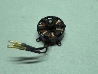
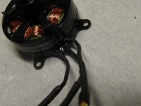
Next, you should install the prop adapter. If you are using GWS props (recommended on Lite aircraft) then you will find that the newer batch of GWS SF props do not have a hex near the hub, they are round. You will need to use a round adapter ring to fit them. The motor comes with two adapter rings, test fit each one to find the correct size and attach it with a tiny dab of Welder glue so it doesn't come off in a crash.
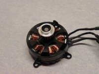
Now mount the motor on the airplane with the supplied screws.
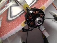
Next, route your aileron servo wire through the fuselage and down to where you will mount the receiver.
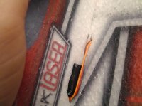
Mount your ESC with a dab of Welder glue...
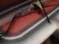
As well as your receiver. Tie the wires up to keep everything compact and tight.
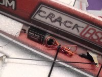
Finally, route the ESC battery wire up through the fuselage, since the battery is mounted on top of the horizontal fuselage on this plane.
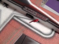
And one final trick: we have found that it's best to cut a slot for the batteries with these planes. They roll more axially and stay more true during pushes and pulls. However, since you will likely want to fool with CG a bit, you only have one shot to mount it in the right place. So, for the first few trimming flights, just hold the battery on with T-pins.
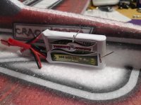
You won't be able to fly really hard but it will be enough to let you figure out if you got your CG right or not. Once you are satisfied with the position, cut a slot and you are good to go!
First, lay out your tools and supplies...a square, Phillips and flat-head screwdrivers, tweezers, CA, the ubiquitous Welder glue, hobby knife with fresh blades, wire cutters, and new for this build: Blenderm tape. Also recommended but not shown is a good set of weights and some parchment paper.

Also pictured is the Twisted Lite Power Combo including 1750 KV motor, 6 amp ESC, 8x4.3 GWS props, 2X CS-40D and 1X CS-90D servos. Also some 360 mah batteries.

Fuselage parts

Wing parts

Tail parts, small foam parts, wheelpants

Hardware pack

The very first thing you should do is fold each hinge back 180 degrees and put a weight on it for a few hours or overnight. This will make the hinges more supple and really help take load off of the servos.

Next let's reinforce the hinges. First cut a small piece of Blenderm tape.

Put a small bead of glue near the end of the hinge line.

Lay the piece of tape on the glue, sticky side down.

Flatten it and press the glue out to the edges of the tape.

You can use your knife like a rolling pin to get it perfectly flat.

The result is an almost invisible reinforcement that won't break. Do this at the ends of the elevator and rudder, and the root and tip of the aileron. There is no need to do it near the inboard counterbalance.

Now let's assemble the wings and horizontal fuselage. Lay out a piece of parchment paper (note: this should really be the same size as the wings).

Test fit the wings together and make sure everything lines up. We will do this assembly upside-down.

Lay a bead of Welder glue on the mating surface the wing...


....press it together to wet both surfaces....

...then pull it apart and let it tack up.

After the glue is tacky but not wet, press the wings together. It will grab tightly.

Cut out the 4 ribs.


Find the spars...they are the long carbon tubes.

Clean out the slots for the spars with a sharp knife.

This is how the spars go in...the short spar goes in first, the longer spar is on top. The bumps on the ribs point out of the bottom of the wing.

Test fit the spars and ribs in to make sure everything fits well.

Spread some glue in the slots for the spars and ribs.

...and then install the spars and ribs. Wipe up any glue that squirts out.

Weight down the assembly and let it dry completely.


Now let's do some optional reinforcement. Lay a bead of glue down across where the wing meets the fuselage...do this in four places: the trailing edge and the leading edge, on both sides.

Now lay a piece of blenderm over these strips of glue. Press it down just like you did with the hinges.

After you repeat this on all four corners, you will have a much stronger fuselage. I find that these models tear here a lot but this really prevents that.

Glue the stab and elevator on the fuselage with the same procedure as the wings.


Add a fillet of glue at the corner of the stab and fuselage. This will help with durability.

Now it's time to install some servos. Plug in all of your electronics and test them.

Here's a trick we have found...spread some glue thinly in the servo cutout and LET IT DRY COMPLETELY.

Do the same on all mating surfaces of the servos, letting them dry completely. When you install them, you can pop them in and they will not move around at all. However they will be much easier to remove than if you had glued them in normally.

Now let's install the aileron horns. Cut them out of the plywood piece and cut the pushrod guides out of the horns.

Store the pushrod guides in the hardware bag...they are easy to lose.

Clean out the slots for the aileron horns on the ailerons.

Install the EZ connectors on the aileron horns.

Make sure the screw hole is point out, away from the fuselage, so you can get to it with a screwdriver.

Now pop in the aileron servo. You may need to gently pull the foam away to work it in there but it will go in.

Do the same for the rudder servo.

Power up the rudder servo to center it, then install the arm. You should also install the EZ-connector on the arm before you install it (not shown here).

Test fit the upper fuse half on the wing and horizontal fuse to make sure everything clears properly.

You will likely have to cut a small clearance for the aileron servo wire.


Spread some glue on the mating surface of the upper fuse half.

Install the upper fuse half...

...and make sure it is lined up correctly.

Once the upper fuse half has dried a bit, hang it off of the edge of your bench.

We can now install the elevator servo. Make sure it is centered, and install the arm and EZ connector. Pop it into the fuselage.

We can now also the aileron arm. Cut it out of the wood parts.

Find the round servo wheel for the aileron servo. The hub fits neatly in the hole of the arm.

Add a little Welder glue to the surface of the round servo wheel and glue it onto the aileron arm. DO NOT LET IT DRY YET.

Before the glue dries, center the aileron servo, and install the arm. Now, with the glue still wet, rotate the aileron arm until it's perfectly aligned. Now you can get full travel and perfect centering without using sub-trim. Install the screw (not shown).

Weight down the wing and install the lower fuselage half. Test fit it with no glue to make sure everything clears.

Then glue it on, and use your square to make sure it's all lined up.

Check the alignment at both ends.

Next, let's install the foam braces that keep the tail torsionally stiff.

Trim the front of one of the braces off to clear the servo wires. Hang on to this piece.


Glue them on carefully, keeping everything aligned.

Next let's glue on the motor mount. Wet it with plenty of Welder glue....I have found there is no need to scuff it.

And stick it on the front of the airplane, lining everything up carefully.

Let it dry a bit. Now, time for another new reinforcement tip...first, smear some Welder glue all around the area behind the motor mount legs.


Cut some blenderm strips maybe 2.5" long, and carefully wrap them around the motor mount and over the glue you just applied.


Repeat on all legs of the motormount. This will keep the front of the plane from tearing off in a really hard crash.

Open up the holes for the motor mount screws with your knife.

Finally, find the piece of the foam tail brace you cut off for wire clearance, and glue it on at the front of the airplane. This will keep the nose stiff and add some reinforcement.

Next let's assemble the landing gear. Get the plywood hockey-stick shaped pieces out of the hardware set, the T-shaped wheelpant mounts, as well as the short carbon axles, wheels, and flat gear legs.

Drill out the axles with a 1/16" bit.

Glue the wood part to the gear leg with a drop of medium or thin CA.


Glue the axle to the other end of the wood part, repeat for the other leg.


Now wrap the wood part and joints with thread. Anything will work; here I am using carbon tow but sewing thread is fine too. After it is wrapped add a drop of thin CA to the thread.

Next slip the wheel onto the axle as well as the T-shaped wheelpant mount. Put a drop of CA on the joint for the wheelpant mount to secure it.

Put the gear legs aside while we install the aileron pushrods...it will be easier this way.
Find the stiff, round rods from the hardware pack, as well as two Z-bent wires, and two pieces of heatshrink tubing. Scuff up the wire with some sandpaper to promote good adhesion.
Put a Z-bent wire on the end of each pushrod with heatshrink.


Add a drop of thin CA where the wire protrudes from the heatshrink. It will wick into the joint and cure.
Next put each pushrod in the aileron arm, and then flex the ailerons to insert the other end of the pushrod into the EZ connector. With everything centered, tighten the screws, and trim off the excess pushrod, leaving about 1/4" extra.


With the gear legs prepared, let's install them on the fuselage. Find the plywood rectangle for the wood parts. There is a cutout on the lower fuse where the gear legs pass through; the rectangle goes between the gear legs at this point. Clean it out with your knife.


After dry-fitting everything, pull it all out a bit, add some glue, and reassemble. Make a good fillet where the ends of the gear legs engage the fuselage (there are holes there).


Now is a good time to install the elevator and rudder horns. These are different than the aileron horns but identical to each other. Pop them out of the hardware package and cut the pushrod guides out of them.

Clean out the slots that are cut for the horns in the surfaces with your knife.

Finally, glue the horns in with some Welder glue.

Next we can do the elevator and rudder pushrods. These are the long carbon rods from your carbon pack. Attach the Z-bends to the rods with heatshrink and CA just like you did with the aileron pushrods, then thread on six of the plywood pushrod guides on each pushrod. Then, insert the Z-bend end into the horn, and push the other end of the pushrod into the EZ-connector on the servo.


Next, carefully find the lasercut holes for the pushrod guides, and carefully glue them into the holes, being sure not to get any glue on the pushrod. You can use either Welder glue or CA here.


Now trim off the excess pushrod length and insert it into the bottom of the fuse to make a tailskid.


Finally, it's a good time now to install the SFG's and T-canalizer. The wing SFG's need to be split before they can be glued on...take care to make sure everything is properly lined up.


Finally, cut a hole in the wheelpants for the axle and glue them on.


Alright, almost there!
Let's prepare the motor for mounting. First, another new tip for longevity: I have often found that after quite a few hard hits, it's not uncommon for motor wires to break. Often this happens just inside the motor and it means that motor is toast.
You can prevent this by adding some Welder glue to the wires where they exit the motor. This fillet of glue will protect the wires and make them last longer.


Next, you should install the prop adapter. If you are using GWS props (recommended on Lite aircraft) then you will find that the newer batch of GWS SF props do not have a hex near the hub, they are round. You will need to use a round adapter ring to fit them. The motor comes with two adapter rings, test fit each one to find the correct size and attach it with a tiny dab of Welder glue so it doesn't come off in a crash.

Now mount the motor on the airplane with the supplied screws.

Next, route your aileron servo wire through the fuselage and down to where you will mount the receiver.

Mount your ESC with a dab of Welder glue...

As well as your receiver. Tie the wires up to keep everything compact and tight.

Finally, route the ESC battery wire up through the fuselage, since the battery is mounted on top of the horizontal fuselage on this plane.

And one final trick: we have found that it's best to cut a slot for the batteries with these planes. They roll more axially and stay more true during pushes and pulls. However, since you will likely want to fool with CG a bit, you only have one shot to mount it in the right place. So, for the first few trimming flights, just hold the battery on with T-pins.

You won't be able to fly really hard but it will be enough to let you figure out if you got your CG right or not. Once you are satisfied with the position, cut a slot and you are good to go!

