You are using an out of date browser. It may not display this or other websites correctly.
You should upgrade or use an alternative browser.
You should upgrade or use an alternative browser.
Redwing 30cc Yak55 Buid Log
- Thread starter GravitySux
- Start date
-
- Tags
- build thread dle35ra redwing savox yak55
GravitySux
30cc
Thanks!
GravitySux
30cc
Hinging the rudder is basically the same as the ailerons and elevator. The only mod that needs to be made is that you will need to grind or sand off 1/4" off of each control arm allowing all 4 to fit into the rudder without hitting each other.


Just apply glue, install hinges and tape in place allowing the glue to cure.....same as before!


Tomorrow, I will install the stabs and hook up the rudder cables!...... opcorn:
Just apply glue, install hinges and tape in place allowing the glue to cure.....same as before!
Tomorrow, I will install the stabs and hook up the rudder cables!......
opcorn:
Last edited by a moderator:
GravitySux
30cc
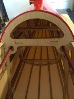
First I installed the rudder servo with the output shaft facing the firewall.

Ok, on to the rudder cables. With the rudder now installed you will need to run the rudder cables. I use an old pushrod and tape the end of the cable to it and feed it through the cable opening. Also, these openings will need to be cut out just like the servo bays in the side of the fuse. If you have trouble locating where to cut, I like to take a covering iron and run it over the area and she should see the opening through the covering....either it will be a lighter color from the heat or it will appear smoother that the surrounding wood structure.

I chose to cross the rudder cables since this is what the offset carbon servo arm provided is for. I like to start with the servo arm first, then move to the rudder pulling the cables tight in the process. One thing I forgot to mention, I found a neat servo centering tool at a swap meet a while back. It runs off of a 4.8v power supply and you can plug in up to 3 servos at a time and center them. This works out great for the rudder because you can leave it plugged in keeping the servo centered and tape the top of the rudder keeping it straight. This way your cables come out nearly perfect from the start!


Ok, on to the rudder cables. With the rudder now installed you will need to run the rudder cables. I use an old pushrod and tape the end of the cable to it and feed it through the cable opening. Also, these openings will need to be cut out just like the servo bays in the side of the fuse. If you have trouble locating where to cut, I like to take a covering iron and run it over the area and she should see the opening through the covering....either it will be a lighter color from the heat or it will appear smoother that the surrounding wood structure.
I chose to cross the rudder cables since this is what the offset carbon servo arm provided is for. I like to start with the servo arm first, then move to the rudder pulling the cables tight in the process. One thing I forgot to mention, I found a neat servo centering tool at a swap meet a while back. It runs off of a 4.8v power supply and you can plug in up to 3 servos at a time and center them. This works out great for the rudder because you can leave it plugged in keeping the servo centered and tape the top of the rudder keeping it straight. This way your cables come out nearly perfect from the start!
Attachments
Last edited by a moderator:
GravitySux
30cc
Once the rudder cables are complete, I installed the stabs. This is pretty straight forward and just requires sliding in the carbon stab tube and attaching each stab with the 4-2.5m allen bolts supplied. My stab tube fit a little on the loose side but this was easily solved with a layer of packing tape run the length of the tube, then everything was snug.

Once the stabs are attached, I installed the elevator servos. Again you will need that long pushrod to fish the wires through the notches in the formers. Once you have the servos installed, I used my centering tool and matched up the splines on the metal wheels that I got from redwing and then installed the carbon arms to them. Once this is done install the pushrod and ball links and adjust till the elevator is neutral.

Once the stabs are attached, I installed the elevator servos. Again you will need that long pushrod to fish the wires through the notches in the formers. Once you have the servos installed, I used my centering tool and matched up the splines on the metal wheels that I got from redwing and then installed the carbon arms to them. Once this is done install the pushrod and ball links and adjust till the elevator is neutral.
GravitySux
30cc
wow Herb this build is coming along nicely. Those CF servo arms are so long, it seems you might be able to move the ball link in one or two holes from the end of the arm to get closer to 90* geometry on the linkages...do you have any opinions on that?
That's a good point! I didn't really think about it until you said it, but yes they could be moved in a hole or so. I will wait and see how the throw comes out once I max out the endpoints on the radio.....I will keep you posted!...
Last edited by a moderator:
GravitySux
30cc
Now that the stabs and rudder are installed its time to move on to installing the DLE 35ra. I had saved a firewall drill guide from an aeroworks kit and it just happened to fit the firewall perfectly. This made drilling the mounting holes extremely easy. All I had to do was line up the cross hatches and all was good.


GravitySux
30cc
Mounting the engine is pretty straight forward, just be sure to add Loctite to the muffler mounting bolts and install the muffler before installing the engine! Also, if you know where your throttle linkage will pass through the firewall, now would be the time to drill that hole too. If not, just temporarily mount the engine and mark where the pushrod will exit the firewall, remove the engine and drill the hole. For my install, I mounted the ignition module on the right side of the motor box placing a thin piece of foam under it and securing it with zip ties.


I mounted the on/off switch on the right side of the fuselage along with the fuel dot and the ignition LED. I will be using one battery (2500mah LiFe) for the ignition and flight systems. The ignition will be controlled from the transmitter utilizing the IBEC. This is my first attempt on using an IBEC so I will keep you posted.

I mounted the on/off switch on the right side of the fuselage along with the fuel dot and the ignition LED. I will be using one battery (2500mah LiFe) for the ignition and flight systems. The ignition will be controlled from the transmitter utilizing the IBEC. This is my first attempt on using an IBEC so I will keep you posted.