You are using an out of date browser. It may not display this or other websites correctly.
You should upgrade or use an alternative browser.
You should upgrade or use an alternative browser.
Aerobeez 26% 74" Slick540 Build, Maiden Log!
- Thread starter Aerobeez
- Start date
Pete
50cc
I started one morning with the intent of a complete build of my Aerobeez 26% Slick540 ARF and maiden the next day! Keep in mind this ARF includes all the hardware and a plumbed ready fuel tank! As I took the parts and components out of the box, I noticed the attention to detail in where each airframe piece was placed and taped in the box. Everything was super secure and the main box was very thick. I laid out my basic build tools a cup of coffee and my build begins. So super excited to get the build going! My first steps, I want to get my Slick on the landing gears so it makes the build easier. I lay out my fuselage on a soft surface and survey my next steps.

I have found the small camping fold-able stools with a towel on top works amazing to hold your fuselage. Of course if you have a large build area and table you can use a Robart style fuselage holder. Here's a tip for you, next time you buy a monitor, or a LCD TV, don't throw away the foam cradles in the box. With a little cutting, they make for a perfect fuselage holder! Aerobeez has really taken some of the difficult and time consuming work out of the new kits such as this Slick540 and others. Getting the landing gear, wheels and wheel pants mounting have never ever been so fast and easy! The included carbon landing gear holes are drilled for you perfectly lining up with the holes in the fuselage. Using 4 bolts, washers and lock nuts, the landing gear quickly mounts to the fuselage. Using all the supplied wheels and hardware, the axles are mounted and wheels in place! The next area where I'm sure many of us builders have struggled has also been made care free. The wheel pant mounting many of us dread. The fear of drilling the holes off slightly will give us very off angle wheel pants or wheels pants that rub or just don't fit! Well no more of that with this ARF! The fiberglass wheel pants are pre drilled! The blind nuts (2 per wheel pant) are already installed and pressed into place! The holes on the landing gear pre drilled as well for a perfect angle and fitment! 2 bolts each side and a drop of blue loctite and done!

In about 10 minutes my Slick is on landing gear!

I then move on to the install of the Rudder. All of the control surfaces on this Slick come glued and gaped right out of the box! Excluding the rudder. The rudder takes 3 pin style hinges. At this point you can do either the step I am on on or you can also install the rudder control surface horns if it makes it easier for you. I chose to install the rudder. I always use a small oil dropper and start by putting a drop right onto the pivot area of the hinge. This will insure the hinge does not glue stuck once you insert them. A few likes to glue one side then oil. I like to drop one drop of oil first. You can use any fine tip oilier, house hold 3n1 oil or if you don't have any of that, a toothpick and a bit of cooking oil will work just fine.

Once the hinges are oiled, make sure there are no oil on your fingers before you grab the hinge. Now insert the hinge into the rudder and check fitment on both the rudder and vertical stabilizer. Once you are satisfies with the fitment, use epoxy to glue them in. Here again, many have their glue of choice. From thick CA, Gorilla Glue or Epoxy. My dad taught me to build with Epoxy in all the crucial areas and I will always use Epoxy on pivot style hinges. Gorilla Glue works but it expands while drying and can cause issues. CA works but can cause issues as well. Epoxy is strong and gives you some working time and is thick enough to fill in the small gaps if there are any. When working with epoxy, always have some denatured alcohol or acetone ready with a small rag. If you are an avid builder, 5 minute epoxy works fine as you are only gluing 3 hinges. I suggest using at least 15 minute epoxy. Give yourself some working time. Once you have your epoxy all mixed nice, use a small stick and apply it to the hinge one at a time only to one side of the pin hinge. Then insert into the rudder. Now is very important to check the rotation of the hinge. Sometimes we get so excited, the pivot angle is wrong and we don't realize it until the glue has set. Check that the other side of the pin is rotating as laterally like a rudder would and not vertically. When you have all 3 hinges in place, let it sit and dry.

Once the hinges are dried in the rudder, I check for smooth hinge movement on each hinge. If needed, ad one more drop of oil to the pivot area. Now go ahead and mix up another batch of epoxy. Apply to each hinge, line up the rudder with the predrilled holes in the fuselage and press into place. I have found that pressing the rudder all the way against the vertical stabilizer then just backing it off every so slightly gave me a great gap. You can rotate the rudder slowly to the amount of throw each direction for your ideal flying style. Now let dry. I have found this Slick as tremendous rudder authority and it does not need 50+ degrees of deflection.

Once the rudder has dried, give it a few rotations to insure smooth movement. Now it is a personal choice to gap seal or not. If you choose to gap seal, you can use clear household tape or what we mostly use is a tape called 3M Blenderm. This process is not needed but if you really want to, you can gap seal. It is sealing the gap the length of the control surface at the root to give even and lower the disturbance in the air flow. Now onto the next step. Installing the tail wheel.

The carbon tail wheel installs to the fuselage with 3 self tapping screws. I however always go the extra step and drill a small 1/16 pilot hole. A few steps and done! The Slick is now on full landing gears!


Next steps I move to installing all of the control surface horns.

The included "sandwich" style fiberglass horns are awesome! The ball push rod ends are strong and uses a single bolt and a lock nut to secure. Very easy to work on! My personal preference when installing the control surface horns, I tend to install all of them in one sitting. Meaning have all of them installed on all the surfaces before moving on to another step. Do this one surface at a time. Remember the ailerons and elevators are already glued for you and gaped. I take each control surface horn and I will tighten the 2.5mm bolt to the nut until snug. This gives both the horns an even gap for easier fit in the glue process. Here's a tip. When gluing fiberglass horns, I will always use a Dremel tool with a coarse tip to "score" the flat areas on both sides where the glue and surface will be in contact with the control surface. You don't have to use a Dremel tool if you don't have one. You can also do just fine with some 400 grit sandpaper or a file. Once you have scored all the control surfaces, you can move on to the next steps. On each control surface, you will find 2 slots for the horns. The covering will need to be cut with a sharp xacto blade or hobby knife. I use my finger and just run it over the area with some pressure and you can feel the slots under the covering. Once you press on it, it will leave indention in where the slots are. Cut the covering away. I have found that the 2 horns in the rudder sit end to end or back to back. They are a bit long. I cut about 3mm from each side for the rudder horns to be glued. You will notice the horns will sit just perfect. Now onto the glue. There are a few glue of choice and they are about the same. One is the think CA wicking method, second the Gorilla Glue method and third the Epoxy method. I know many people have used the CA wicking method with great success. However use a quality CA glue. The Gorilla Glue will leave a ugly foam looking expansion run but very strong. Third and my choice is using Epoxy. I choose 5 min Epoxy and I can glue 2 surfaces on each mix. I believe this to be the strongest of all and clean up if you have residual glue is easy with the Denatured Alcohol or Acetone. Once all your control surface horns are glued we move on.


When your Rudder horns are completely dry and cured, we will run the Pull/Pull Rudder cables. I start by centering and securing the rudder to the vertical stabilizer by using a piece of 3M Blue tape.

There's not really an easy way to describe how to install Pull/Pull cables. The included system uses 2 crimps per control side. So far each pilot seems to have a different method for pull/pull install. I chose to use the provided fiberglass rudder servo extension as seen here. This gives the best resolution and strength for the rudder. XQ Power Servos are used through out my build.

Just make sure the cables are just taut slightly for now. Usually after the maiden or a couple of flights, the cables will need to be tightened a bit by screwing in the ends. Now we move on to install the Elevator servos. The elevator servo bays are factory cut as well. However the covering is still over the area. Go ahead and find that bad with the same method by pressing in the general area. You can also shine a bright flashlight from the inside of the fuselage to show the servo area. I always cut about 1/8" less than the actual size of the bay. I like to use a covering iron and fold down the edges so they adhere clean to the servo bay. Now test fit your servo. Again, I always pre drill pilot holes for each of my servos. This will keep the wood from splitting. Another tip is after I have drilled the pilot holes for both servos, I like to drop a small drop of thin CA into each hole. This keeps the wood strong once you use the servo screws to secure the servo. White craft glue can be used as well but has a longer curing time.

The horizontal stabilizers are held on by 2 screws per side with flat washers and a rubber washer and blind nuts already installed for you inside the fuselage. I love that the tail section is completely removable! Remember to connect the servo extensions to your elevator servos and use the provided connection keeper included in your ARF. You can now either choose to connect your push rods or move on to the next step. I like completing one area then moving one. I have my servos plugged into my receiver, I center the servos, check the directions and connect the pushrods.

A clean and ready to fly tail section on the Slick! Now we move on.

The next steps are really personal preference. You can choose to install the servos into your main wings for the ailerons, mount your engine, or mount your switch/fuel dot etc. I like to complete the fuselage before moving on to the aileron servos. Our engine of choice in this build is the DLE-35RA. Just a super reliable and powerful combo for this Slick. However, this Slick is very light and a DLE-30 would be more than enough power. The DLE-35RA was just the engine I had not being used at this time so she's going in my Slick!

The firewall on the Slick has the mounting hole locations for a DLE-30 already circled in place. Yet another time saving bonus! We spend a ton of time to mount our motors to make sure they are centered. The down and right thrust is also built into the firewall. You just basically mount your engine! If you choose a DLE-30 or DLE-35RA the stock stand offs are included with DLE motors and are the perfect length! You drill the holes and mount your engine. It's really that easy. Note: If you use a 35RA 2 of the holes will not line up and 2 are the same as a DLE-30. The easiest way to do this to mark the area to drill the other 2 holes is fairly easy. I drill the 2 holes that do line up first. I then just mount the motor with 2 screws. Just tighten enough so the motor is tight against the firewall. I then just use a thin Sharpie marker and trace as close as I can to the 2 stand offs that needs to be drilled. Before you remove the motor, be sure to mark the area you will need to drill an additional hole for your throttle arm linkage..I then remove the motor and you can see the 2 circles you just traced. Put a dot right in the center of the circles and drill a pilot hole. Then drill your suggested hole size for the bolts. There done! Now mount your motor to the firewall. I choose to always add Loctite to my motor bolts. Whether you use blue or red, any Loctite is better than not using Loctite. If you use Red, keep in mind to use a tiny amount as red is suppose to be permanent. On larger bolts, they can still be broken free.

Next is mounting the throttle servo. Included is a throttle servo tray. The position of the throttle servo is left to be decided by the owner. Due to the different manufactures on engines on the market, the throttle arm on the carburetor are in a different area from engine to engine. Find the best area to mount your throttle servo where it lines up the best to your carburetor linkage.
I will now mount my fuel tank. The included fuel tank is already plumbed and ready for your fuel line. I decided to use a 16ozTITUDE Tank from Aerobeez. Plug and play simplicity at it's best. Clear fuel tank with clunk/filter installed. I just run my fuel lines to the carburetor, the breather and to my fuel dot. The area for the fuel tank already as Velcro and straps. If you choose to use the provided tank, you just attach your fuel lines. If you choose to use a 4TITUDE tank or any other tank, you will need to add a strip of velcro on the tank (the fuzzy soft side).


Here is a photo of the Miracle Switch with built in fuel dot already mounted. An Aluminum Fuel dot is included with this ARF Slick if you choose to use. Switch choice and fuel dot choice/location is personal preference.

I now test fit the gorgeous fiberglass cowl. The cowling in held on by 4 small bolts using a cowl retainer ring. This mounting method is clean and there are no visible screws on the exterior of the Slick holding the cowl. The 2 screws are to be mounted inside the cowl. I choose to use a long 2.5mm ball end driver. You can also tighten these 2 screws by drilling a small hole in the cowl or by using extensions. Before you are able to screw down your cowl, we will need to cut the openings for the motor, cooling in necessary and exhaust. The best way I have found is by shining a bright flash light under the cowl and using a sharpie mark the shadow area to be cut. There are several methods of course. I have just found this one to be the easiest. I then always cut the areas smaller than my lines traced. Always easier to remove more material than removing too much from the get go. I use a Dremel with a cut off dish. Once I test fit and I am happy with the mounting area, I will use a smooth round Dremel bit to clean up the edges. This will keep the paint from cracking as well on sharp corners. Round them off and they are less likely to crack.
A perfect fit! Using the holes already marked gives us a perfect fit! I love it when something works just as planned!

Now I will install my aileron servos. Same method as the elevator servos! Just repeat the cut and iron process. If you choose not to iron, you can cut the exact cut out size. If you choose that route, use a bit of clear tap on each side to keep the covering from pealing back.

Now set up your push rods!

We are now on the home stretch! You can choose to run any spinner you personally like. I like the bling factor so I chose a 3.5" Carbon Spinner from Aerobeez. Also they are very light and strong! Propeller is personal choice as well with your engine of choice. We are running a XOAR 20x8 with the DLE-35RA.


Now for the remaining steps! Install your flight batteries and the Side Force Generators (SFG's) included with this Slick540! Install is optional of course. The blind nuts are in place in the wing tip. If you choose not to use the SFG's do not cure the area for the screw. I installed them because I think it looks more sporty on the ground! Kind of like a race car parked but looks like it's going fast! Of course there are performance benefits with the SFG's. Better Knife Edge performance, locked in harriers etc.

The build is not complete! Once over on all the linkages, charge the onboard flight batteries and its maiden time! This Slick540 is just stunning in looks and performance! I find myself just starring at how pretty this airplane is. The build was straight forward with no confusing areas that I encountered. Of course everyone is going to ask the dreaded where's the CG question. Here is my thoughts on CG. Is it important? Of course it is. However I think many people really over analyze and emphasize CG with a bunch of technical numbers and data. My dad taught me a simple rule. One person on each side of the main wing, on any normal wing configuration, find the wing spar start at about 1/2" behind the wing spar, use your finger and lift the airplane with the batteries and half tank of fuel. I don't like to over analyze too much so here is what I have. My tank location can be seen in the photos above. I use one 2200mAh 2s Lipo direct as the XQ Power Servos I am using are High Voltage. The lipo is right next to my fuel tank. I am using a IBEC for my ignition so I have no ignition battery. Below I will talk about the maiden flight.
Here's right after the minty fresh build!


One thing I do want to mention is the build on the 30% 88" 50-60cc Aerobeez Slick540 is pretty much the same. Only difference I can remember are the tail servos in the 30% are mounted inside the horizontal stabilizer instead of the fuselage.
Continued Below:

I have found the small camping fold-able stools with a towel on top works amazing to hold your fuselage. Of course if you have a large build area and table you can use a Robart style fuselage holder. Here's a tip for you, next time you buy a monitor, or a LCD TV, don't throw away the foam cradles in the box. With a little cutting, they make for a perfect fuselage holder! Aerobeez has really taken some of the difficult and time consuming work out of the new kits such as this Slick540 and others. Getting the landing gear, wheels and wheel pants mounting have never ever been so fast and easy! The included carbon landing gear holes are drilled for you perfectly lining up with the holes in the fuselage. Using 4 bolts, washers and lock nuts, the landing gear quickly mounts to the fuselage. Using all the supplied wheels and hardware, the axles are mounted and wheels in place! The next area where I'm sure many of us builders have struggled has also been made care free. The wheel pant mounting many of us dread. The fear of drilling the holes off slightly will give us very off angle wheel pants or wheels pants that rub or just don't fit! Well no more of that with this ARF! The fiberglass wheel pants are pre drilled! The blind nuts (2 per wheel pant) are already installed and pressed into place! The holes on the landing gear pre drilled as well for a perfect angle and fitment! 2 bolts each side and a drop of blue loctite and done!

In about 10 minutes my Slick is on landing gear!

I then move on to the install of the Rudder. All of the control surfaces on this Slick come glued and gaped right out of the box! Excluding the rudder. The rudder takes 3 pin style hinges. At this point you can do either the step I am on on or you can also install the rudder control surface horns if it makes it easier for you. I chose to install the rudder. I always use a small oil dropper and start by putting a drop right onto the pivot area of the hinge. This will insure the hinge does not glue stuck once you insert them. A few likes to glue one side then oil. I like to drop one drop of oil first. You can use any fine tip oilier, house hold 3n1 oil or if you don't have any of that, a toothpick and a bit of cooking oil will work just fine.

Once the hinges are oiled, make sure there are no oil on your fingers before you grab the hinge. Now insert the hinge into the rudder and check fitment on both the rudder and vertical stabilizer. Once you are satisfies with the fitment, use epoxy to glue them in. Here again, many have their glue of choice. From thick CA, Gorilla Glue or Epoxy. My dad taught me to build with Epoxy in all the crucial areas and I will always use Epoxy on pivot style hinges. Gorilla Glue works but it expands while drying and can cause issues. CA works but can cause issues as well. Epoxy is strong and gives you some working time and is thick enough to fill in the small gaps if there are any. When working with epoxy, always have some denatured alcohol or acetone ready with a small rag. If you are an avid builder, 5 minute epoxy works fine as you are only gluing 3 hinges. I suggest using at least 15 minute epoxy. Give yourself some working time. Once you have your epoxy all mixed nice, use a small stick and apply it to the hinge one at a time only to one side of the pin hinge. Then insert into the rudder. Now is very important to check the rotation of the hinge. Sometimes we get so excited, the pivot angle is wrong and we don't realize it until the glue has set. Check that the other side of the pin is rotating as laterally like a rudder would and not vertically. When you have all 3 hinges in place, let it sit and dry.

Once the hinges are dried in the rudder, I check for smooth hinge movement on each hinge. If needed, ad one more drop of oil to the pivot area. Now go ahead and mix up another batch of epoxy. Apply to each hinge, line up the rudder with the predrilled holes in the fuselage and press into place. I have found that pressing the rudder all the way against the vertical stabilizer then just backing it off every so slightly gave me a great gap. You can rotate the rudder slowly to the amount of throw each direction for your ideal flying style. Now let dry. I have found this Slick as tremendous rudder authority and it does not need 50+ degrees of deflection.

Once the rudder has dried, give it a few rotations to insure smooth movement. Now it is a personal choice to gap seal or not. If you choose to gap seal, you can use clear household tape or what we mostly use is a tape called 3M Blenderm. This process is not needed but if you really want to, you can gap seal. It is sealing the gap the length of the control surface at the root to give even and lower the disturbance in the air flow. Now onto the next step. Installing the tail wheel.

The carbon tail wheel installs to the fuselage with 3 self tapping screws. I however always go the extra step and drill a small 1/16 pilot hole. A few steps and done! The Slick is now on full landing gears!


Next steps I move to installing all of the control surface horns.

The included "sandwich" style fiberglass horns are awesome! The ball push rod ends are strong and uses a single bolt and a lock nut to secure. Very easy to work on! My personal preference when installing the control surface horns, I tend to install all of them in one sitting. Meaning have all of them installed on all the surfaces before moving on to another step. Do this one surface at a time. Remember the ailerons and elevators are already glued for you and gaped. I take each control surface horn and I will tighten the 2.5mm bolt to the nut until snug. This gives both the horns an even gap for easier fit in the glue process. Here's a tip. When gluing fiberglass horns, I will always use a Dremel tool with a coarse tip to "score" the flat areas on both sides where the glue and surface will be in contact with the control surface. You don't have to use a Dremel tool if you don't have one. You can also do just fine with some 400 grit sandpaper or a file. Once you have scored all the control surfaces, you can move on to the next steps. On each control surface, you will find 2 slots for the horns. The covering will need to be cut with a sharp xacto blade or hobby knife. I use my finger and just run it over the area with some pressure and you can feel the slots under the covering. Once you press on it, it will leave indention in where the slots are. Cut the covering away. I have found that the 2 horns in the rudder sit end to end or back to back. They are a bit long. I cut about 3mm from each side for the rudder horns to be glued. You will notice the horns will sit just perfect. Now onto the glue. There are a few glue of choice and they are about the same. One is the think CA wicking method, second the Gorilla Glue method and third the Epoxy method. I know many people have used the CA wicking method with great success. However use a quality CA glue. The Gorilla Glue will leave a ugly foam looking expansion run but very strong. Third and my choice is using Epoxy. I choose 5 min Epoxy and I can glue 2 surfaces on each mix. I believe this to be the strongest of all and clean up if you have residual glue is easy with the Denatured Alcohol or Acetone. Once all your control surface horns are glued we move on.


When your Rudder horns are completely dry and cured, we will run the Pull/Pull Rudder cables. I start by centering and securing the rudder to the vertical stabilizer by using a piece of 3M Blue tape.

There's not really an easy way to describe how to install Pull/Pull cables. The included system uses 2 crimps per control side. So far each pilot seems to have a different method for pull/pull install. I chose to use the provided fiberglass rudder servo extension as seen here. This gives the best resolution and strength for the rudder. XQ Power Servos are used through out my build.

Just make sure the cables are just taut slightly for now. Usually after the maiden or a couple of flights, the cables will need to be tightened a bit by screwing in the ends. Now we move on to install the Elevator servos. The elevator servo bays are factory cut as well. However the covering is still over the area. Go ahead and find that bad with the same method by pressing in the general area. You can also shine a bright flashlight from the inside of the fuselage to show the servo area. I always cut about 1/8" less than the actual size of the bay. I like to use a covering iron and fold down the edges so they adhere clean to the servo bay. Now test fit your servo. Again, I always pre drill pilot holes for each of my servos. This will keep the wood from splitting. Another tip is after I have drilled the pilot holes for both servos, I like to drop a small drop of thin CA into each hole. This keeps the wood strong once you use the servo screws to secure the servo. White craft glue can be used as well but has a longer curing time.

The horizontal stabilizers are held on by 2 screws per side with flat washers and a rubber washer and blind nuts already installed for you inside the fuselage. I love that the tail section is completely removable! Remember to connect the servo extensions to your elevator servos and use the provided connection keeper included in your ARF. You can now either choose to connect your push rods or move on to the next step. I like completing one area then moving one. I have my servos plugged into my receiver, I center the servos, check the directions and connect the pushrods.

A clean and ready to fly tail section on the Slick! Now we move on.

The next steps are really personal preference. You can choose to install the servos into your main wings for the ailerons, mount your engine, or mount your switch/fuel dot etc. I like to complete the fuselage before moving on to the aileron servos. Our engine of choice in this build is the DLE-35RA. Just a super reliable and powerful combo for this Slick. However, this Slick is very light and a DLE-30 would be more than enough power. The DLE-35RA was just the engine I had not being used at this time so she's going in my Slick!

The firewall on the Slick has the mounting hole locations for a DLE-30 already circled in place. Yet another time saving bonus! We spend a ton of time to mount our motors to make sure they are centered. The down and right thrust is also built into the firewall. You just basically mount your engine! If you choose a DLE-30 or DLE-35RA the stock stand offs are included with DLE motors and are the perfect length! You drill the holes and mount your engine. It's really that easy. Note: If you use a 35RA 2 of the holes will not line up and 2 are the same as a DLE-30. The easiest way to do this to mark the area to drill the other 2 holes is fairly easy. I drill the 2 holes that do line up first. I then just mount the motor with 2 screws. Just tighten enough so the motor is tight against the firewall. I then just use a thin Sharpie marker and trace as close as I can to the 2 stand offs that needs to be drilled. Before you remove the motor, be sure to mark the area you will need to drill an additional hole for your throttle arm linkage..I then remove the motor and you can see the 2 circles you just traced. Put a dot right in the center of the circles and drill a pilot hole. Then drill your suggested hole size for the bolts. There done! Now mount your motor to the firewall. I choose to always add Loctite to my motor bolts. Whether you use blue or red, any Loctite is better than not using Loctite. If you use Red, keep in mind to use a tiny amount as red is suppose to be permanent. On larger bolts, they can still be broken free.

Next is mounting the throttle servo. Included is a throttle servo tray. The position of the throttle servo is left to be decided by the owner. Due to the different manufactures on engines on the market, the throttle arm on the carburetor are in a different area from engine to engine. Find the best area to mount your throttle servo where it lines up the best to your carburetor linkage.
I will now mount my fuel tank. The included fuel tank is already plumbed and ready for your fuel line. I decided to use a 16ozTITUDE Tank from Aerobeez. Plug and play simplicity at it's best. Clear fuel tank with clunk/filter installed. I just run my fuel lines to the carburetor, the breather and to my fuel dot. The area for the fuel tank already as Velcro and straps. If you choose to use the provided tank, you just attach your fuel lines. If you choose to use a 4TITUDE tank or any other tank, you will need to add a strip of velcro on the tank (the fuzzy soft side).


Here is a photo of the Miracle Switch with built in fuel dot already mounted. An Aluminum Fuel dot is included with this ARF Slick if you choose to use. Switch choice and fuel dot choice/location is personal preference.

I now test fit the gorgeous fiberglass cowl. The cowling in held on by 4 small bolts using a cowl retainer ring. This mounting method is clean and there are no visible screws on the exterior of the Slick holding the cowl. The 2 screws are to be mounted inside the cowl. I choose to use a long 2.5mm ball end driver. You can also tighten these 2 screws by drilling a small hole in the cowl or by using extensions. Before you are able to screw down your cowl, we will need to cut the openings for the motor, cooling in necessary and exhaust. The best way I have found is by shining a bright flash light under the cowl and using a sharpie mark the shadow area to be cut. There are several methods of course. I have just found this one to be the easiest. I then always cut the areas smaller than my lines traced. Always easier to remove more material than removing too much from the get go. I use a Dremel with a cut off dish. Once I test fit and I am happy with the mounting area, I will use a smooth round Dremel bit to clean up the edges. This will keep the paint from cracking as well on sharp corners. Round them off and they are less likely to crack.
A perfect fit! Using the holes already marked gives us a perfect fit! I love it when something works just as planned!

Now I will install my aileron servos. Same method as the elevator servos! Just repeat the cut and iron process. If you choose not to iron, you can cut the exact cut out size. If you choose that route, use a bit of clear tap on each side to keep the covering from pealing back.

Now set up your push rods!

We are now on the home stretch! You can choose to run any spinner you personally like. I like the bling factor so I chose a 3.5" Carbon Spinner from Aerobeez. Also they are very light and strong! Propeller is personal choice as well with your engine of choice. We are running a XOAR 20x8 with the DLE-35RA.


Now for the remaining steps! Install your flight batteries and the Side Force Generators (SFG's) included with this Slick540! Install is optional of course. The blind nuts are in place in the wing tip. If you choose not to use the SFG's do not cure the area for the screw. I installed them because I think it looks more sporty on the ground! Kind of like a race car parked but looks like it's going fast!
Of course there are performance benefits with the SFG's. Better Knife Edge performance, locked in harriers etc. 
The build is not complete! Once over on all the linkages, charge the onboard flight batteries and its maiden time! This Slick540 is just stunning in looks and performance! I find myself just starring at how pretty this airplane is. The build was straight forward with no confusing areas that I encountered. Of course everyone is going to ask the dreaded where's the CG question. Here is my thoughts on CG. Is it important? Of course it is. However I think many people really over analyze and emphasize CG with a bunch of technical numbers and data. My dad taught me a simple rule. One person on each side of the main wing, on any normal wing configuration, find the wing spar start at about 1/2" behind the wing spar, use your finger and lift the airplane with the batteries and half tank of fuel. I don't like to over analyze too much so here is what I have. My tank location can be seen in the photos above. I use one 2200mAh 2s Lipo direct as the XQ Power Servos I am using are High Voltage. The lipo is right next to my fuel tank. I am using a IBEC for my ignition so I have no ignition battery. Below I will talk about the maiden flight.
Here's right after the minty fresh build!


One thing I do want to mention is the build on the 30% 88" 50-60cc Aerobeez Slick540 is pretty much the same. Only difference I can remember are the tail servos in the 30% are mounted inside the horizontal stabilizer instead of the fuselage.
Continued Below:
Pete
50cc
Here we go! Some photos of maiden day!


To the Runway for the maiden!

My Dad at the camera grips both video and photos!

Take Off! (My knees were chattering!)

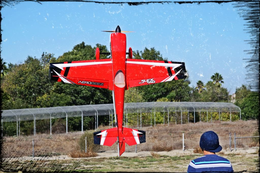
Airborne!


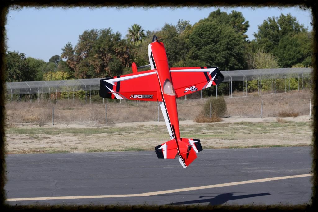
Upon take off I felt one thing right away. Slight back on the elevator and she was smooth as she leaves the runway. 3 clicks of up elevator and clicks of rudder trim was all she took! She was flying super level and so very smooth! I proceed to climb a bit to pull an inverted fly by CG check. I roll inverted and she stayed pretty neutral! She did pull towards the canopy a bit so this tells me she's a tad on the nose heavy side. Which is not bad at all given the 16oz 4TITUDE was full! I then perform some vertical up lines, 45 degree climbs to check a few things and then a Knife Edge fly by. WOW! The Knife Edge I felt almost no knife edge coupling at all! Straight and I just guided her by steering with the elevator and minimal input on the rudder! Once more I climb a bit into a Knife Edge slide to a slow and low high alpha knife edge. So very stable and precise right over the runway! I then of course had to start some hucking. I first check harriers. Keep in mind she's a bit on the nose heavy side so initially there was a bit of wing rock which later on I found the sweet spot angle where this Slick just locks into a harrier and you just just steer her with the rudder and pop the throttle. Next inverted harrier was almost too floaty! No wing rocking at all! Pop into a hover and it was basically LOVE. That's all I can say! I fly out of the hover and pull some high energy maneuvers. Snap rolls stops on a dime! 1 1/2 Snaps to inverted stops super clean into snap to knife edge and snap out. So super precise! No time for some tumbles and Pop Tops! The Pop Tops are awesome! Either orientation Pop Tops either direction she rotates like crazy! I did a few Pin Wheel Pops otherwise named the "Spin Cycle" by my buddy Matt Stringer and it was time to land and check some screws etc. Landing was as buttery as can be. Pretty much almost hands off if it wasn't for the cross winds. Here are a few more photos!


Here is the video of a later in the week flight! Keep in mind everyone, I'm just an average pilot and not a 3D Guru like some of the pilots! I just love to fly and love to share the experience! Thanks for checking out this semi build log!
[video=youtube;DKWTHAxWFOk]http://www.youtube.com/watch?v=DKWTHAxWFOk&feature=c4-overview&list=UU_r5C9Y5a4ijXotyKhZqBrA[/video]
Regards,
Pete
-Aerobeez 26% Slick540: http://aerobeez.com/74-26-Slick-540-30cc-Gas-ARF-RC-Airplane-Red.html
-DLE-35RA: http://aerobeez.com/DLE-35RA-35cc-Gas-Engine-With-2.13-Cu-in-Displacement-Full-Package.html
-XQ Power 4116D On Elevator and Aileron: http://aerobeez.com/XQ-POWER-HIGH-VOLTAGE-DIGITAL-SERVO-15KG-CM-56G-XQ-S4116D.html
-XQ Power 4120D on Rudder: http://aerobeez.com/XQ-POWER-HIGH-VOLTAGE-DIGITAL-SERVO-18KG-CM-56G-XQ-S4120D.html
-Miracle Switch with Fuel Dot: http://aerobeez.com/RC-ACCESSORIES-SWITCHES/
-Miracle 1.5" Aluminum Arms: http://aerobeez.com/Miracle-RC-Heavy-Duty-1.5-Half-Servo-Arm-For-Futaba-Purple.html
-4TITUDE 16oz Tank: http://aerobeez.com/FOURTITUDE-RC-16OZ-FUEL-TANK-JASON-DANHAKL.html
-Aerobeez Carbon Fiber Spinner: http://aerobeez.com/Carbon-Fiber-Spinner-3-5-inch-Short-Pre-cut-2-blades.html
-Miracle Servo Extensions: http://aerobeez.com/Accessories-Servo-Extensions/


To the Runway for the maiden!

My Dad at the camera grips both video and photos!

Take Off! (My knees were chattering!)

Airborne!


Upon take off I felt one thing right away. Slight back on the elevator and she was smooth as she leaves the runway. 3 clicks of up elevator and clicks of rudder trim was all she took! She was flying super level and so very smooth! I proceed to climb a bit to pull an inverted fly by CG check. I roll inverted and she stayed pretty neutral! She did pull towards the canopy a bit so this tells me she's a tad on the nose heavy side. Which is not bad at all given the 16oz 4TITUDE was full! I then perform some vertical up lines, 45 degree climbs to check a few things and then a Knife Edge fly by. WOW! The Knife Edge I felt almost no knife edge coupling at all! Straight and I just guided her by steering with the elevator and minimal input on the rudder! Once more I climb a bit into a Knife Edge slide to a slow and low high alpha knife edge. So very stable and precise right over the runway! I then of course had to start some hucking. I first check harriers. Keep in mind she's a bit on the nose heavy side so initially there was a bit of wing rock which later on I found the sweet spot angle where this Slick just locks into a harrier and you just just steer her with the rudder and pop the throttle. Next inverted harrier was almost too floaty! No wing rocking at all! Pop into a hover and it was basically LOVE. That's all I can say! I fly out of the hover and pull some high energy maneuvers. Snap rolls stops on a dime! 1 1/2 Snaps to inverted stops super clean into snap to knife edge and snap out. So super precise! No time for some tumbles and Pop Tops! The Pop Tops are awesome! Either orientation Pop Tops either direction she rotates like crazy! I did a few Pin Wheel Pops otherwise named the "Spin Cycle" by my buddy Matt Stringer and it was time to land and check some screws etc. Landing was as buttery as can be. Pretty much almost hands off if it wasn't for the cross winds. Here are a few more photos!


Here is the video of a later in the week flight! Keep in mind everyone, I'm just an average pilot and not a 3D Guru like some of the pilots! I just love to fly and love to share the experience! Thanks for checking out this semi build log!
[video=youtube;DKWTHAxWFOk]http://www.youtube.com/watch?v=DKWTHAxWFOk&feature=c4-overview&list=UU_r5C9Y5a4ijXotyKhZqBrA[/video]
Regards,
Pete
-Aerobeez 26% Slick540: http://aerobeez.com/74-26-Slick-540-30cc-Gas-ARF-RC-Airplane-Red.html
-DLE-35RA: http://aerobeez.com/DLE-35RA-35cc-Gas-Engine-With-2.13-Cu-in-Displacement-Full-Package.html
-XQ Power 4116D On Elevator and Aileron: http://aerobeez.com/XQ-POWER-HIGH-VOLTAGE-DIGITAL-SERVO-15KG-CM-56G-XQ-S4116D.html
-XQ Power 4120D on Rudder: http://aerobeez.com/XQ-POWER-HIGH-VOLTAGE-DIGITAL-SERVO-18KG-CM-56G-XQ-S4120D.html
-Miracle Switch with Fuel Dot: http://aerobeez.com/RC-ACCESSORIES-SWITCHES/
-Miracle 1.5" Aluminum Arms: http://aerobeez.com/Miracle-RC-Heavy-Duty-1.5-Half-Servo-Arm-For-Futaba-Purple.html
-4TITUDE 16oz Tank: http://aerobeez.com/FOURTITUDE-RC-16OZ-FUEL-TANK-JASON-DANHAKL.html
-Aerobeez Carbon Fiber Spinner: http://aerobeez.com/Carbon-Fiber-Spinner-3-5-inch-Short-Pre-cut-2-blades.html
-Miracle Servo Extensions: http://aerobeez.com/Accessories-Servo-Extensions/
Last edited by a moderator:


bbrown2828
150cc
does the aero beez plane not come with a gear cover.. I am building the redwing 30cc right now and it had one
gyro
GSN Contributor
does the aero beez plane not come with a gear cover.. I am building the redwing 30cc right now and it had one
It does not, however they told me that is planned for inclusion on the next revision.