Aerobeez
70cc twin V2

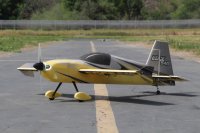
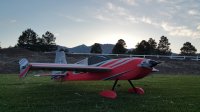
Hello pilots and welcome to our Step By Step Build guide for the 55" EDGE 540 EPP Hybrid! This Edge 540 EPP Hybrid is one of the easiest and most straight forward build ARF's ever and we are happy to help walk you through each step as we would. In this build log, team pilot Pete will take you step by step in building your new Edge 540. So now, without further ado, let's start the build!
Step 1
Use a hobby knife and cut the portion of the foam to install the landing gear. Only cut one side that has 2 shorted pre-slit cuts. You will be bending the foam over to install the carbon fiber landing gear. Removing the entire foam area is not necessary.

Step 2
Remove the EPP foam cut outs on the bottom of the fuselage. These are precut and can be simply pressed out. These holes are pre-cut for electronics cooling.

Step 3
Now make note that the leading edge of the main landing gear will be straight and the trailing edge will be tapered. So once the landing gear is mounted, the leading edge will point towards the nose and the trailing edge will point toward the tail.

Step 4
Install the carbon landing gear with the screws provided in the hardware bag.

Step 5
Install the wheel axles, wheels and wheel pants. Keep the set screw on the wheel collar in a vertical position. This will make adjusting the wheel collar position much easier.


Step 6
Glue on the landing gear "fairings" with CA or rubber cement. There are four pieces total, two per side. One on the bottom and one on the top side of the landing gear. Basically "sandwich" the carbon gear between the foam fairings.

Step 7
Remove the pieces as seen in these photos for the inserting of the horizontal stabilizer. DO NOT DISCARD the back piece! This will be glued back once the horizontal stabilizer and elevator has been glued to the fuselage.


Step 8
Apply CA on the horizontal stabilizer in the center area on both top and bottom. Insert into the fuselage slot.
Note: Use thick CA if you are using this step. Medium or Thin CA will dry too quickly and you may not be able to insert the tail section all the way before the glue adheres.

Step 9
When the horizontal elevator is in position, use thin or medium CA and run a bead of glue to the outside where the tail section meets the fuselage. Repeat this step for both top and bottom.

Step 10
Install the elevator and press in all the way.

Step 11
Using Thin CA, soak each CA hinge and allow to dry.

step 12
Glue the piece previously cut out of the vertical stabilizer back into place once the elevator hinges have completely dried.


Step 13
Now glue the vertical stabilizer support brace into position. Best method is to press the elevator full down, insert the brace into position and drop medium CA onto the brace. If you apply glue to the brace prior to inserting, you will have glue all over your fingers. Be sure to press the brace firmly and check the elevator for clearance in up and down travel.


Step 14
Install the rudder and using thin CA, apply to the rudder hinges.


Step 15
Glue the elevator, rudder, aileron control surface arms into place using medium to thick CA or Epoxy.


Step 16
Install the tail wheel assembly.

Step 17
We will now install the motor box. However before we apply glue, text fit the motor box to the fuselage. Note: The top of the motor box has three alignment tabs. The bottom has four alignment tabs.

Step 18
Once the motor box is in position, you will notice the "right thrust" on the firewall. This angle is pre-cut from our factory.

Step 19
When the motor box is in position, use medium or thick CA and apply to the perimeter of all four sides of the motor box.

Step 20
Triangular wood stocks are provided for reinforcing the motor box for torsion strength. Glue all the triangular stocks to the motor box with epoxy or CA on all four sides. The shorter wood stocks are for the firewall area.

Step 21
Apply medium or thick CA to the trailing edge main wing root and press onto the main wing. Using thick CA, you may wick the glue to the joint area.


Step 22
Glue the ailerons to main wing using the same steps as the previous control surfaces.

Step 23
Remove the foam and the wood from the front and rear section of the cowling.


Step 24
The blind nuts are pre-installed for your motor X mount. This will allow for easy mounting of your motor.

Step 25
Use the included wood motor mount spacers to adjust for the motor clearance when the cowling is installed.


Step 26
Install your servos and pushrods, set your servo pushrod lengths.


Step 27
If you choose to use them, install the SFG's for added stability in knife edge and other aerobatic maneuvers. SFG's are personal preference and are included as an optional feature.
Your build is not complete!


Be sure to program your EPA/Travel Adjust, set your subtrims/dual rates, and always range check!
Happy Flying!
If you have any questions, please ask!
Thank you as always for reading our build blog and for your patronage and support.
Your Hobby, Our Passion!
Aerobeez
Attachments
Last edited by a moderator:


