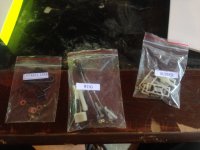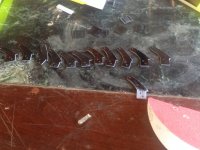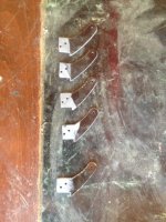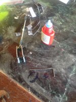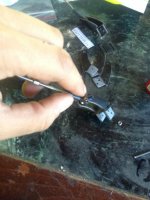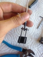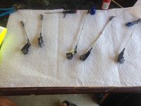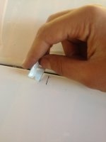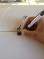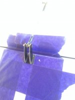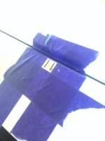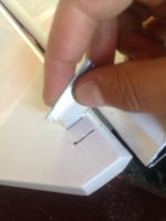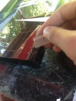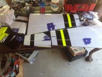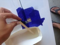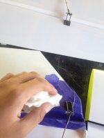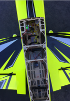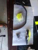
Now locate your carbon fiber landing gear, wheel pants, gear cuffs, and landing gear accessory bag.
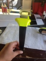
Slide the gear cuffs onto the landing gear, make sue its on the correct way. The front of the landing gear is the flat side, the rear is a bit tapered as you can see in the picture above. The right side of the gear in the picture is the front. The shortest part of the gear cuff should be in the front of the rear, the rear part of the cuff extends out a little bit more for looks. Do not glue in the cuffs yet!
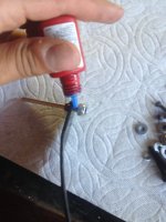
Now screw in the axle into the carbon fiber landing gear. Make sure to put locktite on the threads of the axle!
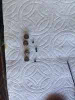
Find all four of the wheel collars and take them out of the bag. Remove all of the set screws and lay them out on the table.
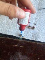
Put locktite in all of the collars where the set screw goes in, this is a very important step! Without the locktite the set screws are bound to vibrate loose!
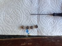
Put the set screws into the collars but do not tighten all the way.
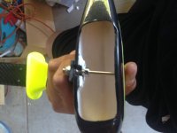
Slide the collar onto he axle, do not tighten i yet. Put the wheel pant where it is supposed to be in order to determine the distance between the collar and the axle.
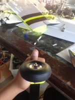
Once you have determined the proper distance for the collar to be tighten the collar, slide on the wheel, slide on the other collar and tighten. Repeat the same steps for the other side.
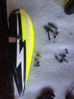
Aerobeez has taken the liberty of putting the blind nut in the wheel pants for you, but i do not like putting the wheel pants on the landing gear just yet because i do not want them to get scratched. So put in your bolts in the wheel pants and keep them in a safe place until he end.
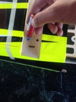
Flip the airplane over to its underside, remove the gear cover from where it is supposed to be and put Locktite in the holes where the blind nuts are.
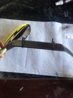
Now slide the landing gear bolts through the landing gear.
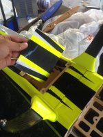
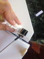
Bolt everything in place and make sure that that everything fits together nicely. At this point you can also remove the tape holding the hatch i the back as shown in the picture above.
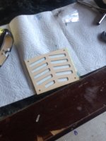
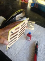
Lay the hatch out upside down on a table, and with a sharp knife cut away the covering from the slots.
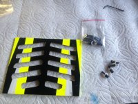
Find the four screws that are supposed to hold the hatch in place.
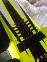
Put Locktite on the bolts and screw them in place.
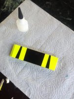
At this point we can glue the landing gear cover in place. For this step you can use Epoxy or CA. I used CA but Epoxy is recommended.
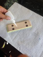
Put your choice of glue on the bottom side of the landing gear cover plate.
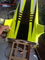
Now glue it in place.
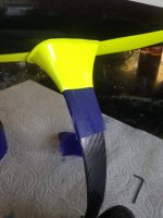
Move your gear cuffs to the desired location and put a few strips of masking tape on the bottom of the gear cuff.
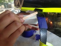
Slide down the gear cuff and place some epoxy on the place where the gear cuff meets the landing gear.
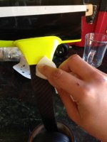
Slide the gear cuff in place, remove the masking tape, and clean up excess epoxy.
Repeat these steps for both sides.
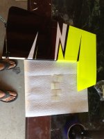
Now we can hinge the rudder. (NOTE: The kit comes with four hinges but only three slots in the rudder for hinges, while i only used three hinges and it has worked out well for me, i do recommend cutting an extra slot on the top or bottom of the rudder for an extra hinge)
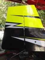
Temporally slide in your hinges to your rudder and make sure everything fits and spaces out in your desired locations.
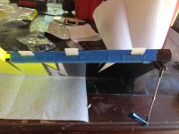
Using masking tape mask the area around the hinges on the rudder side.
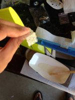
To put the glue on the hinges, i recommend using at least a 20minute Epoxy give you time to work and clean the airplane from any epoxy marks that may happen. Put some Epoxy on the hinge as well as the slot in the rudder. Repeat this step for all of your hinges.
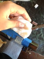
Using a wet paper towel wet with Acetone, clean around the hinge knuckles that may have Epoxy on them. At this point remove the masking tape, clean the areas again and put on new masking tape in the same manner as before all while the glue is still wet.
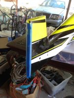
Mask the vertical stabilizer in the same way that we masked the rudder.
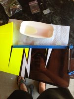
Once you have allowed the hinges in the rudder dry for at least one hour, you can put epoxy on the other side of the hinge that is going into the vertical stabilizer. Also put epoxy in the slots of the vertical stabilizer.
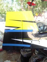
You may now slide in the rudder, remove the masking tape, clean the area and tape the rudder and vertical stabilizer together in the same manner i have showed in the picture.
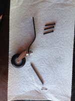
Now locate your tail wheel assembly, spring, wood screw, and the three bolt all supplied with the kit. Aerobeez took the liberty of pre-installing the tail wheel on the tail wheel assembly to help you get your plane flying just a little bit faster!
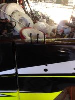
Poke out the holes on the bottom of the plane where the blind nuts for the tail wheel have already been installed for you.
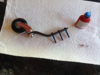
Slide the bolts into the tail wheel assembly and put locktit on the threads of all the bolts.
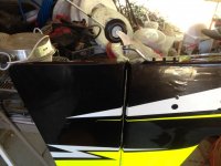
Bolt the tail wheel assembly in place.
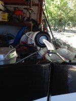
Put the end of the spring hole into the hole on the tail wheel assembly.
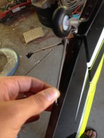
Stretch the spring until you feel a little bit of tension.
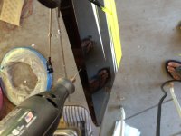
Using a small drill bit drill a small starter hole where the end of the spring would be.
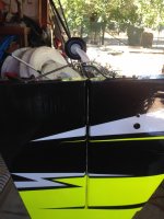
With the wood screw supplied with the kit screw in the screw into the hole in the spring and into the starter hole we drilled in the rudder.
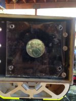
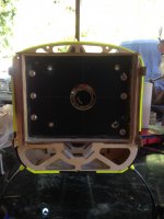
At this point we can install the motor. Using your motor template line them up with the lines on the firewall and drill through.
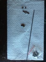
Locate your throttle push rod (Should be taped to your wing tube), ball link and the other motor installation parts that are supplied with your kit. I took off the carburetor arm from my engine to make this next step a little easier. I suggest you do this as well.
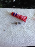
Using locktite,lockite the ball link screw into the throttle arm.
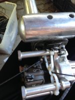
Connect the throttle arm back to the engine and screw in the push rod.
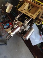
Drill out any other of the holes you need to make you motor fit, and install your motor on the plane. USE RED LOCKTITE!!! (NOTE: Depending on what engine you use, if you use a standard 50cc engine with the stock stand offs the spinner gap will be to far away, so you will need shorter stand offs. This also means that with the shorter stand offs you might have to cut out a large opening in the firewall for your engines carburetor to fit.)
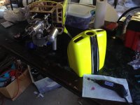
Find your cowl and a dremel because the next step is to cut the cowl to fit your engine.
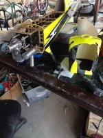
Slide your cowl over the engine and begin cutting away until all of your engine can fit through the cowl without rubbing on any part.
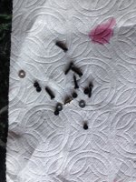
Locate the bolt set for your cowl.
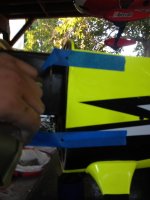
Put masking tape over where the blind nut are located on the fuselage and mark the whole with a sharpie. Repeat these steps on both sides.
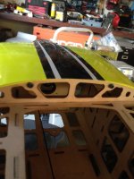
Slide on the cowl and tighten the two bolts on the inside to keep the cowl on.
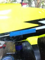
Slide the tape that we marked before over the cowl. (NOTE: I decided to only drill out the bottom hole and not both the top and bottom, i only chose this for convenience and a cleaner look but using both are recommended) Drill where the mark is with a 2.5mm drill bit and put the screws in. Repeat these steps on both sides.
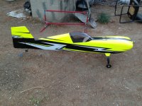
We now have something that almost looks like an airplane!
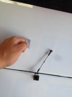
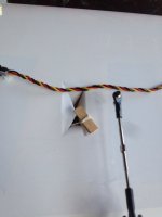
We can now begin installing servos! Cut the covering in an x shape where the servo is located on the wing. Break off the little piece of wood with the string going though it.
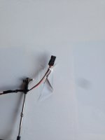
Tie the servo extension for your aileron servo to this white string.
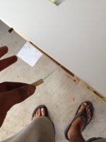
Pull the servo extension through. By the white string on the other side.
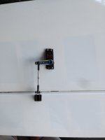
Now install your servo to the control horn. Remember to use locktite!
Repeat these steps to both wings.
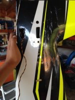
Cut the servo hole for the rudder and elevators. The rudder servo location is directly under the elevators and the elevator servo locations are directly in front of the elevators on either side of the fuselage. On the right side of the fuselage inside the tail, there is the piece of string used to run the servo extensions to the fuselage.
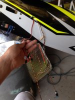
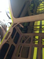
Tie all of your servo extensions together and run your wires though the fuselage using the piece of sting inside the fuselage (Picture shown above)
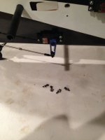
Now you can install all of your tail servos. Locate all four of the 2.5mm bolts used to hold on the elevators. Connect your rudder servo arm to the push rod. Remember to use locktite!
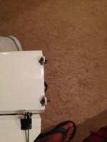
Put the screws into the elevator tabs on the bottom and put locktite on the screws!
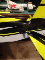
You may now install the elevators and elevator push rods on both sides. Remember to loctite everything!
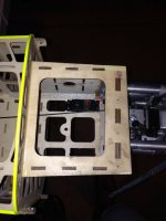
Now we can install the throttle servo. For my 50cc setup i found this the best place to put my throttle servo.
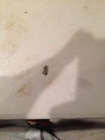
Now find this piece inside the the motor screw accessory bag. The throttle push rod will slide into this piece.
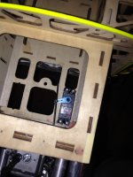
Connect your throttle servo to you motor.
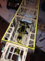
We can now install our tank. Aerobeez has made this step super easy by having the fuel tank pre plumbed. All you need to do is take out the extra o-rings that are in the bottle, make sure the bottle is closed tightly with the o-ring in place, add a little velcro to the bottom of the tank, and strap the tank in place! Make sure to run a vent line out side the plane, and to run the motor line into the carburetor.
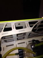
Inside the fuselage you can locate this little hole, this is for you fuel dot.
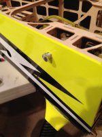
Cut away the covering and screw in the fuel dot that Aerobeez has supplied in the kit.
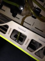
Make sure to tighten the nut on the inside of the fuselage for the fuel dot.
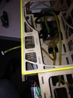
Run the line from your tank into the fuel dot.
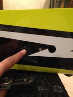
For the aileron servo extension to make its way into the fuselage, cut a little slit right behind the whole for the wing tube screw. By cutting a slit, this makes the plane look a little nicer without having extra holes.
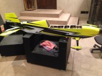
Now you can go ahead and install your wheel pants.
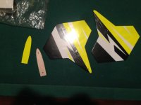
You can choose to fly with or with out side force generators. I chose to fly with them.
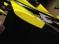
There are blind nuts pre installed in the wing for the use of SFG'S.
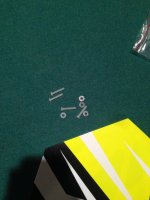
These are the screws used for the SFG's.
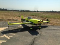
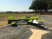
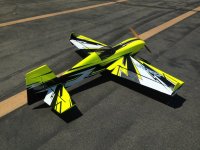
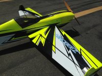
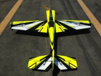
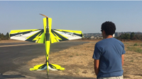
You are now complete with your Aerobeez 78" Radien Extra 330sc! Happy Flying!
PRO TIPS:
CG-
Using a 50cc engine with the rudder servo in the rear and a Gens Ace 3500mAh 2s RX pack strapped onto the wing tube i got the CG to balance a little bit behind the wing tube. On the tip of the wing the CG is right in front of the aileron counter balance. I know that this seems a bit tail heavy but i find that this air frame fly's best with the CG a little bit behind the wing tube.
Throws:
For 3D throws i recommend starting off on the elevators and rudder at around 55degrees, and the ailerons at around 30degrees. I generally start off with around 60% expo on the radio. Work your way from these measurements at roughly 5degree increments.
For low rates i recommend setting everything at around 20degrees with around 50% expo and work your way from there at roughly 3degree increments.
Final Thoughts:
I personally believe that Aerobeez hit the nail on the head with this airplane! They practically built most of the plane for you right out of the box! I have flown many airplanes, and i have to say that this plane is my favorite all around plane. It fly's true, tumbles great, fly's precise, and rolls fast! But when you turn down the rates a bit, it fly's like a big trainer! Really happy about how this plane came out!Looking forward to flying it some more!
-Orel Elbaz
