AZAerobat
50cc
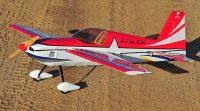
Welcome to my first build log! My name is AZAerobat (AZ is because I am an Arizona native) or you can call me by my street name Matt! First a little background, I have been building and flying R/C planes since I was 12 years old so that is almost 20 years now. I only recently dove head first into 3D flight about 2 1/2 years ago. My first balsa 3D bird was the formidable "Buck Huck" AKA the 41" Edge 540 from 3D Hobby Shop. Some time passed I fell in love with the look of their blue 48" Edge 540 and had to have one so I bought my second 3DHS plane. Some more time passed, like it always does, and I won a 71" AJ Slick in a raffle. It took a while to save up for the gear to go inside it and I recently finished it last spring. After the 71 Slick I decided I wanted to try an Extreme Flight design and pre-order the 64" Green MXS as a birthday gift to myself. I finished assembling it right before the winter hit and have only had about 7 flights on it to date. So basically I have assembled three 3DHS balsa ships and one EF.
I recently sold my 41" Edge to pursue a 42" AJ Slick because the rumor mill stated they would be coming stateside. Well the rumor ended and I jumped on the pre-order list for one ASAP. I decided to document my experiences and assembly of the 42" Slick for all to enjoy so let me know how it goes.
List of Gear Being Used
Motor - Omega 103g
Prop - Xoar 12X6 Beechwood Electric
ESC - ZTW B Series 45Amp
Servos - 2 Hitec HS 65HB's for Ailerons and 2 Hitec HS 65MG's for Elevator and Rudder
Battery - Sky Lipo 1600 3S 40C
TX/RX - Spektrum DX8 and AR600 DSMX
First things first, go and download the instruction manual. I downloaded mine to a tablet so I could refer to it in my work area. Next gently unpack everything from your box. Use an xacto knife or a pair of scissors to cut the tape freeing the separate packages in the box. DO NOT try to yank them out. Remember you are dealing with balsa and fiberglass. These planes are built tough but you still need to be fairly careful.
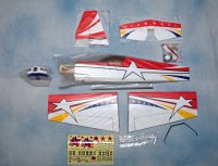
This step is optional but if you have a heat gun or a covering iron go ahead and tighten up the covering on all of your pieces before you start your build.
Next I like to take either a brand new xacto blade out or a soldering iron with an old tip that I will never use again and cut out all of the holes in the fuselage, wings, and control surfaces.
The landing gear comes next. I like to file or grind a little flat spot onto the axles so that the wheel collars have a flat surface to lock down to.
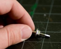
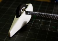
Grab your 2 wheels, 2 axles, 2 wheel pants (if you want to they are just for looks anyways), 2 wheel collars, and your carbon fiber gear and put them all together. Assemble each axle, wheel and wheel collar first. Then attach them loosely to the landing gear so you can attach the pants and tighten the assemblies down. My wheels rubbed a little bit on the wheel pants so I ended up shaving the slightest little bit out of the pants until the wheels did not rub anymore. The take the landing gear and bolt it onto the fuselage with Blue Loctite.
Guess I forgot to photograph these next few steps, whoops. Find your vertical stabilizer, mine was attached to the rudder, and glue it onto the fuse with a good amount of medium or thick CA.
Next grab your elevator and horizontal stabilizer and separate them. Insert the elevator into the slot upside down and backwards then turn it over in the slot. Next slide the horizontal stabilizer in and attach the elevator to the horizontal stab. You can go ahead and glue in the hinges now if you want to but I prefer to glue the stab in first. Attach the wings to your fuse and check for proper alignment of your elevator with a yard stick or a tape measure.
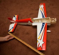
Once you have the same distance on both sides glue in the top and the bottom of stab using thin CA. Do not worry about the covering getting in the way. It will attached to the fuse with no issues.
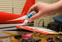
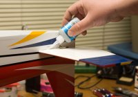
Now I like to do my hinges. If you do not have an applicator tip for your thin CA I highly recommend one even if you only use it for hinges. Thin CA flows out fast like a freshly tapped keg at happy hour on a Friday night! Too much thin CA on the hinge can bind up your servo and cause problems along with not getting the maximum throw out of your control surface. Use 1 -2 drops of CA per hinge on top and on bottom of the elevator. Let the hinges dry completely before you mess with the elevator again.
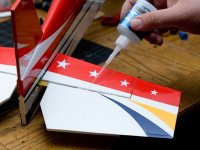
While we are at it might as well do the other hinges. We have our nice tip on our bottle so let's not waste it. Attach the rudder, set the hinge gap to get as much throw as possible and glue your hinges like above. A couple of drops on each hinge on each side of the rudder.
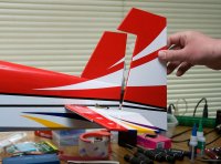
Grab your wings, check your ailerons from maximum throw, and finally glue in your hinges here too on both wings.
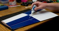
While we still have our thin CA out it is a good idea to go over each seem in the motor box. 3DHS builds amazing ARF's but since the motor box is probably the most high stress area on the plane it is a good idea to go over every seem you can reach for some added strength.
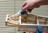
Grab your razor blade and cut the covering off of the area on the rudder where the tail wheel wire will be inserted. Line up the tail wheel wire exactly with the hinge line so the tail wheel will not cause binding. Using your knife or a tiny (and I mean tiny) drill bit cut or drill a small hole for the bent portion of the tail wheel wire to be inserted into. Glue the wire into the rudder with thick CA.
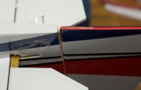
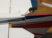
Next install the pivot plate onto the tail wheel wire. If you notice in my photo my pivot plate it smaller then the stock one well that is because I cut one of the holes off. I learned this weight saving trick from Ben Fisher's 41" Edge 540 build videos on YouTube. With the larger airframes you need to have more than one screw to hold the tail wheel on but as he pointed out these smaller frames really do not need the extra screw and you can save some weight here if you want to. This step or tip is totally optional. Make sure the rudder moves freely without any friction or binding before screwing down the plate. You might have to drill out the pivot plate if the wire does not slide easily through it. Attach the tail wheel and wheel collar. I used a little more Blue Loctite here. Medium CA works well too if you do not have any Loctite.
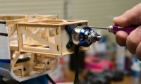
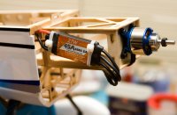
Before attaching the motor to your firewall Loctite the different screws on the motor such as the screws for the X mount and the screws for the prop holder. Attach the motor to the firewall using Blue Loctite again. If your X mount holes do not line up with the pre drilled holes in the firewall you will have to drill new ones
Attach your ESC. I like to Zip tie mine to the motor box. The zip ties make it easy to remove if I have to adjust the center of gravity later and the battery is just not enough to change your CG. I also like to put a tube of heat shrink over each bullet connector for just a little bit more peace of mind.
The cowl is attached next with 4 screws. First install your canopy and put a strip of blue painters tape or any other tape that does not leave a residue on the very front of it. This will help keep the cowl from being too tight on the canopy. Next get 2 pieces of tape about 4 -6 inches long and cut them in half. Find the little plywood squares on the inside of the cowl area and mark them with the pieces of tape extending past the squares. These strips will mark where you will drill your holes along with holding the cowl in place.
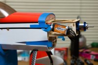
Install the cowl and attach the strips. If you are going to be using a spinner attach it and set your gap. I tend to get crazy with the tape here but I do not want the cowl coming loose and messing up my gap. I almost always use a spinner I really like the look of them.
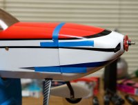
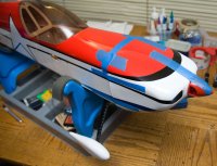
Using your razor blade or a small drill bit make 4 holes through the cowl and into the plywood squares.
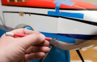
Screw the cowl to the fuselage. Then remove the screws one at a time and drip a drop or two of thin CA on the holes you just made and let it dry. This will help harden the hole so that the screws will bite down better into the wood.
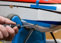
Locate and install the rudder control horn and the elevator control horn using medium or thick CA. Rough up the control horns with a little bit of sandpaper to get a better bond with the CA. You have to make a choice now. You can either mount a pull pull rudder or a push pull rudder. I went with a pull pull setup since it takes some weight out of the tail. The pull pull control horn goes through one side of the rudder and comes out the other.

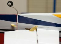
Installing a pull pull rudder is the most difficult thing for me. I always seem to mess something up with it. It does not help that I have giant hands either. Locate the different parts for the pull pull setup and assemble them. Attach two pushrod retainers onto your servo arm and insert two pull pull cable holders.
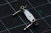
Next install two pull pull cable holders into two ball links.
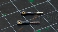
I install the servo side first because of my large hands. It is easier for me to tighten the cables at the rudder then trying to do it inside the fuse. Loop the cable through the cable holders and into a metal crimp. Loop the cable one more time into the metal crimp and use a pair of pliers to crimp everything together. Put a drop of thin CA into the crimp and cables to lock everything down. Do this one more time for the other side of the servo arm.
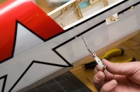
Next attach the ball links onto the control horn and loop the cable through the cable retainer. Make sure that the cable creates an X pattern inside the fuselage. 3DHS already installed the cable and it should be setup this way from the start just double check and make sure. Attach the cables and crimp them down like you did with the servo arm side. Make sure that the you have the same length of wire going to each side of the control horn. You want the cables to be snug but not super tight like a guitar string. The rudder should not move freely without the servo moving as well.
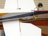
Next install your elevator servo. Use some thin CA again to harden the holes you make with your screws to help the servo lock into place.
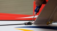
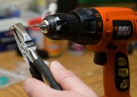
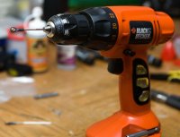
Attach the elevator linkage to a ball link. This can be tricky at times. What I have figured out is to take a drill and install the linkage into the drill like it is a drill bit. Hold the ball link with a pair of pliers and slowly "drill" the linkage into the ball link. Find the aileron linkages and ball links as well and assemble them the same way.
Cut out the covering for your aileron servos and control horns on both wings. Glue the control horns in with some medium or thick CA. Attach the pushrod retainers to their respective servo arms using thick CA to hold them in place. The retainer should move freely on the servo arm without binding. Attach the ball link and pushrod to the control horn, install the servo, and tighten everything down. Do this for both wings.
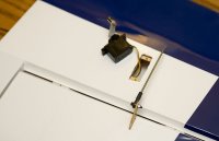
Another way to save some weight after you have all of your linkages installed and ready to go is to go back and shorten the pushrods on the elevator and ailerons. Do not cut them all the way to the push rod retainer you want to leave a fair amount of the push rod past the retainer. This is an optional step for those of you who are trying to save some weight.
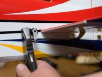
Attach yourself some vinyl you are almost done! I like to clean my plane with some water before I lay down my vinyl.
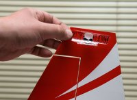
After putting on your vinyl check your center of gravity. A good starting center of gravity (from the manual) is 90mm from the leading edge of the wing where the wing meets the fuselage. The Slick balances upright.
Last setup your control throws. Everyone is different so I am going to go with the what the instruction manual suggests.
Control Throws, measured in degrees and millimeters at trailing edge of surface:
Ailerons: Low 15 degrees, 25mm High 30 degrees, 45mm
Elevator: Low 15 degrees, 20mm High 45 degrees, 65mm
Rudder: Low 30 degrees, 40mm High As much as possible.
Final Thoughts:
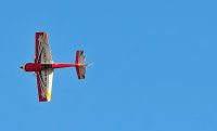
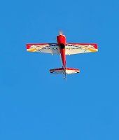
I hope this build was helpful to those who need it. If you have any questions or need any help or further explanation feel free to send me a PM. I will be adding a little bit of a flight review to this build in the future. I maidened the Slick today but I would like to get in more flights before I review it. A couple of complaints I had with the build, I really do mean a couple, one is the tail wheel size. This is not new for me. I personally think all of the tail wheels on all of my 3DHS planes are too small. I understand they are trying to save weight but I still think they are too small. I have replaced most of the tail wheels on my other 3DHS planes and will probably replace this one as needed in the future. The only other issue I had with my ARF was the covering. This has been discussed in the past but this is my only 3D Hobby Shop ARF to have this problem. There is a thin layer of plastic that has peeled off of the trim on the slick. Mainly on just the black or blue covering and only where it was used as trim. The large pieces of covering were fine but the pinstripe sized covering did peel off. If you catch it before it peels off too far you can just simply iron it back down with not problems. It does not affect the flying or even the look of the covering it was just weird to me that it was happening at all.
Overall it was a quick and easy build just like all of my other 3DHS planes. They have their kit building down to an art. Thank you 3D Hobby Shop for making the time from the UPS man showing up at my door to running out to the field to go fly the baby AJ Slick easy, smooth, and fast.
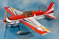
I recently sold my 41" Edge to pursue a 42" AJ Slick because the rumor mill stated they would be coming stateside. Well the rumor ended and I jumped on the pre-order list for one ASAP. I decided to document my experiences and assembly of the 42" Slick for all to enjoy so let me know how it goes.
List of Gear Being Used
Motor - Omega 103g
Prop - Xoar 12X6 Beechwood Electric
ESC - ZTW B Series 45Amp
Servos - 2 Hitec HS 65HB's for Ailerons and 2 Hitec HS 65MG's for Elevator and Rudder
Battery - Sky Lipo 1600 3S 40C
TX/RX - Spektrum DX8 and AR600 DSMX
First things first, go and download the instruction manual. I downloaded mine to a tablet so I could refer to it in my work area. Next gently unpack everything from your box. Use an xacto knife or a pair of scissors to cut the tape freeing the separate packages in the box. DO NOT try to yank them out. Remember you are dealing with balsa and fiberglass. These planes are built tough but you still need to be fairly careful.

This step is optional but if you have a heat gun or a covering iron go ahead and tighten up the covering on all of your pieces before you start your build.
Next I like to take either a brand new xacto blade out or a soldering iron with an old tip that I will never use again and cut out all of the holes in the fuselage, wings, and control surfaces.
The landing gear comes next. I like to file or grind a little flat spot onto the axles so that the wheel collars have a flat surface to lock down to.

Grab your 2 wheels, 2 axles, 2 wheel pants (if you want to they are just for looks anyways), 2 wheel collars, and your carbon fiber gear and put them all together. Assemble each axle, wheel and wheel collar first. Then attach them loosely to the landing gear so you can attach the pants and tighten the assemblies down. My wheels rubbed a little bit on the wheel pants so I ended up shaving the slightest little bit out of the pants until the wheels did not rub anymore. The take the landing gear and bolt it onto the fuselage with Blue Loctite.

Guess I forgot to photograph these next few steps, whoops. Find your vertical stabilizer, mine was attached to the rudder, and glue it onto the fuse with a good amount of medium or thick CA.
Next grab your elevator and horizontal stabilizer and separate them. Insert the elevator into the slot upside down and backwards then turn it over in the slot. Next slide the horizontal stabilizer in and attach the elevator to the horizontal stab. You can go ahead and glue in the hinges now if you want to but I prefer to glue the stab in first. Attach the wings to your fuse and check for proper alignment of your elevator with a yard stick or a tape measure.

Once you have the same distance on both sides glue in the top and the bottom of stab using thin CA. Do not worry about the covering getting in the way. It will attached to the fuse with no issues.


Now I like to do my hinges. If you do not have an applicator tip for your thin CA I highly recommend one even if you only use it for hinges. Thin CA flows out fast like a freshly tapped keg at happy hour on a Friday night! Too much thin CA on the hinge can bind up your servo and cause problems along with not getting the maximum throw out of your control surface. Use 1 -2 drops of CA per hinge on top and on bottom of the elevator. Let the hinges dry completely before you mess with the elevator again.

While we are at it might as well do the other hinges. We have our nice tip on our bottle so let's not waste it. Attach the rudder, set the hinge gap to get as much throw as possible and glue your hinges like above. A couple of drops on each hinge on each side of the rudder.

Grab your wings, check your ailerons from maximum throw, and finally glue in your hinges here too on both wings.

While we still have our thin CA out it is a good idea to go over each seem in the motor box. 3DHS builds amazing ARF's but since the motor box is probably the most high stress area on the plane it is a good idea to go over every seem you can reach for some added strength.

Grab your razor blade and cut the covering off of the area on the rudder where the tail wheel wire will be inserted. Line up the tail wheel wire exactly with the hinge line so the tail wheel will not cause binding. Using your knife or a tiny (and I mean tiny) drill bit cut or drill a small hole for the bent portion of the tail wheel wire to be inserted into. Glue the wire into the rudder with thick CA.

Next install the pivot plate onto the tail wheel wire. If you notice in my photo my pivot plate it smaller then the stock one well that is because I cut one of the holes off. I learned this weight saving trick from Ben Fisher's 41" Edge 540 build videos on YouTube. With the larger airframes you need to have more than one screw to hold the tail wheel on but as he pointed out these smaller frames really do not need the extra screw and you can save some weight here if you want to. This step or tip is totally optional. Make sure the rudder moves freely without any friction or binding before screwing down the plate. You might have to drill out the pivot plate if the wire does not slide easily through it. Attach the tail wheel and wheel collar. I used a little more Blue Loctite here. Medium CA works well too if you do not have any Loctite.

Before attaching the motor to your firewall Loctite the different screws on the motor such as the screws for the X mount and the screws for the prop holder. Attach the motor to the firewall using Blue Loctite again. If your X mount holes do not line up with the pre drilled holes in the firewall you will have to drill new ones

Attach your ESC. I like to Zip tie mine to the motor box. The zip ties make it easy to remove if I have to adjust the center of gravity later and the battery is just not enough to change your CG. I also like to put a tube of heat shrink over each bullet connector for just a little bit more peace of mind.

The cowl is attached next with 4 screws. First install your canopy and put a strip of blue painters tape or any other tape that does not leave a residue on the very front of it. This will help keep the cowl from being too tight on the canopy. Next get 2 pieces of tape about 4 -6 inches long and cut them in half. Find the little plywood squares on the inside of the cowl area and mark them with the pieces of tape extending past the squares. These strips will mark where you will drill your holes along with holding the cowl in place.

Install the cowl and attach the strips. If you are going to be using a spinner attach it and set your gap. I tend to get crazy with the tape here but I do not want the cowl coming loose and messing up my gap. I almost always use a spinner I really like the look of them.


Using your razor blade or a small drill bit make 4 holes through the cowl and into the plywood squares.

Screw the cowl to the fuselage. Then remove the screws one at a time and drip a drop or two of thin CA on the holes you just made and let it dry. This will help harden the hole so that the screws will bite down better into the wood.

Locate and install the rudder control horn and the elevator control horn using medium or thick CA. Rough up the control horns with a little bit of sandpaper to get a better bond with the CA. You have to make a choice now. You can either mount a pull pull rudder or a push pull rudder. I went with a pull pull setup since it takes some weight out of the tail. The pull pull control horn goes through one side of the rudder and comes out the other.


Installing a pull pull rudder is the most difficult thing for me. I always seem to mess something up with it. It does not help that I have giant hands either. Locate the different parts for the pull pull setup and assemble them. Attach two pushrod retainers onto your servo arm and insert two pull pull cable holders.

Next install two pull pull cable holders into two ball links.

I install the servo side first because of my large hands. It is easier for me to tighten the cables at the rudder then trying to do it inside the fuse. Loop the cable through the cable holders and into a metal crimp. Loop the cable one more time into the metal crimp and use a pair of pliers to crimp everything together. Put a drop of thin CA into the crimp and cables to lock everything down. Do this one more time for the other side of the servo arm.

Next attach the ball links onto the control horn and loop the cable through the cable retainer. Make sure that the cable creates an X pattern inside the fuselage. 3DHS already installed the cable and it should be setup this way from the start just double check and make sure. Attach the cables and crimp them down like you did with the servo arm side. Make sure that the you have the same length of wire going to each side of the control horn. You want the cables to be snug but not super tight like a guitar string. The rudder should not move freely without the servo moving as well.

Next install your elevator servo. Use some thin CA again to harden the holes you make with your screws to help the servo lock into place.

Attach the elevator linkage to a ball link. This can be tricky at times. What I have figured out is to take a drill and install the linkage into the drill like it is a drill bit. Hold the ball link with a pair of pliers and slowly "drill" the linkage into the ball link. Find the aileron linkages and ball links as well and assemble them the same way.


Cut out the covering for your aileron servos and control horns on both wings. Glue the control horns in with some medium or thick CA. Attach the pushrod retainers to their respective servo arms using thick CA to hold them in place. The retainer should move freely on the servo arm without binding. Attach the ball link and pushrod to the control horn, install the servo, and tighten everything down. Do this for both wings.

Another way to save some weight after you have all of your linkages installed and ready to go is to go back and shorten the pushrods on the elevator and ailerons. Do not cut them all the way to the push rod retainer you want to leave a fair amount of the push rod past the retainer. This is an optional step for those of you who are trying to save some weight.

Attach yourself some vinyl you are almost done! I like to clean my plane with some water before I lay down my vinyl.

After putting on your vinyl check your center of gravity. A good starting center of gravity (from the manual) is 90mm from the leading edge of the wing where the wing meets the fuselage. The Slick balances upright.
Last setup your control throws. Everyone is different so I am going to go with the what the instruction manual suggests.
Control Throws, measured in degrees and millimeters at trailing edge of surface:
Ailerons: Low 15 degrees, 25mm High 30 degrees, 45mm
Elevator: Low 15 degrees, 20mm High 45 degrees, 65mm
Rudder: Low 30 degrees, 40mm High As much as possible.
Final Thoughts:
I hope this build was helpful to those who need it. If you have any questions or need any help or further explanation feel free to send me a PM. I will be adding a little bit of a flight review to this build in the future. I maidened the Slick today but I would like to get in more flights before I review it. A couple of complaints I had with the build, I really do mean a couple, one is the tail wheel size. This is not new for me. I personally think all of the tail wheels on all of my 3DHS planes are too small. I understand they are trying to save weight but I still think they are too small. I have replaced most of the tail wheels on my other 3DHS planes and will probably replace this one as needed in the future. The only other issue I had with my ARF was the covering. This has been discussed in the past but this is my only 3D Hobby Shop ARF to have this problem. There is a thin layer of plastic that has peeled off of the trim on the slick. Mainly on just the black or blue covering and only where it was used as trim. The large pieces of covering were fine but the pinstripe sized covering did peel off. If you catch it before it peels off too far you can just simply iron it back down with not problems. It does not affect the flying or even the look of the covering it was just weird to me that it was happening at all.
Overall it was a quick and easy build just like all of my other 3DHS planes. They have their kit building down to an art. Thank you 3D Hobby Shop for making the time from the UPS man showing up at my door to running out to the field to go fly the baby AJ Slick easy, smooth, and fast.

Last edited by a moderator:

