You are using an out of date browser. It may not display this or other websites correctly.
You should upgrade or use an alternative browser.
You should upgrade or use an alternative browser.
Build Log Top Flite P-40E Warhawk Gold Edition kit
- Thread starter rcdude07
- Start date
rcdude07
70cc twin V2
awesome work and pics...always exciting to see a kit build start to yield recognizable components of the airframe!
really enjoying watching this one, thanks for posting the updates.
Online my screen name/user name is preferred. Wife prefers to keep a little anonymity for safety these days.
Thanks for the compliments. Yes, taping the elevators to the stab and seeing the iconic P-40 tail shape was exciting.
rcdude07
70cc twin V2
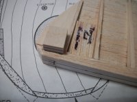
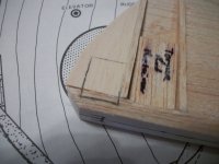
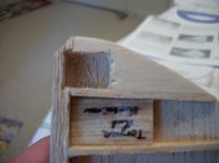
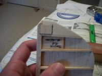
This weekend's work was only about 30 minutes for a small piece, but a critical piece if I want my elevators to work. I installed the plywood piece where the control horn goes on the bottom of the right elevator.
Here's the pics of cutting out the pocket and epoxying the in the plywood for the elevator control horn.
Steps I followed to do so:
1. measure the location from the LE of the elevator to get the LE of the pocket
2. Place the plywood piece in position according to the plans
3. Trace the edges of the plywood piece with a pencil or felt tip pen
4. Use a super sharp #11 Xacto knife to cut the perimeter
5. Using the Xacto knife, cut away at angles to start pulling balsa out
6. Use a Dremel tool with appropriate attachment to clean out the glue and rest of balsa down to the elevator base.
7. Clean the corners of the pocket with the Xacto knife
8. Test fit, trim as needed.
9. Test fit one more time
10. Mix up the 5 minute epoxy, slather it on 5 of the 6 sides of the plywood piece and place in the pocket. Wipe up excess epoxy while pressing and holding the plywood in position. Once epoxy starts setting and wood is not pushing out any when letting go, leave it be over night.
The next night I broke out the 220 grit sandpaper and sanded the top of the plywood to be flush with the elevator root tip.


SnowDog
Moderator
Nice work...sometimes 30 minutes is all we have...nice to finish a specific step in that time...means progress at least!
Since the plywood piece is used to secure the elevator control horn does that mean the elevator joiner will be placed in the area next to the plywood block you just installed? Also, what reinforcement, if any, will be used with the joiner?
Since the plywood piece is used to secure the elevator control horn does that mean the elevator joiner will be placed in the area next to the plywood block you just installed? Also, what reinforcement, if any, will be used with the joiner?
rcdude07
70cc twin V2
Nice work...sometimes 30 minutes is all we have...nice to finish a specific step in that time...means progress at least!
Since the plywood piece is used to secure the elevator control horn does that mean the elevator joiner will be placed in the area next to the plywood block you just installed? Also, what reinforcement, if any, will be used with the joiner?
If you look in the pictures of my previous post you will see a small block of balsa glued between 2 elevator ribs. There is one block on both sides. This is how the slot area for the joiner is reinforced. Remembering back while growing up the joiner gets, or I expect, expoxied in after covering and before pinning the hinges.
After consulting with my dad, I'm deviating from the manual right now. Instead of following the steps of attaching the balance blocks and shaping, shaping LE, joiner holes and LE shaping, and hinge slots. I am doing the following:
1. Joiner holes and LE slots
2. hinges now if I feel like it, with hinges i'm not going to use. this is to not wear off the fuzz on the CA hinges since that's what bonds to the wood
3. wait until final sanding, then do the balance blocks
4. then shape the LE to a V.
rcdude07
70cc twin V2
I got about a good 3 hours worth of work on the bird this weekend from Friday night through Sunday afternoon. Work completed includes the elevator joiner wire fitted in the elevators and the rudder being built. Elevator joiner wire was easy, just used a drill bit to drill the holes as well as wallow out the LE of the elevators so it sits in nice and neat. As you can see from the pictures, the build up of the rudder is the same as the elevators. This time I made sure to mark the rib locations on both sides of the rudder base. You can also see I marked the rudder rib locations better than I did the elevators. Next up is to shape the rudder.
After consulting with my dad who has built 2 Top Flite warbirds his recommendation was to deviate from the plans when it came to the elevator counter balance blocks and shaping the LE of the elevators. It's easier to do the final sanding when the control surfaces hinged and taped flat (no shaping) than with the LE of the elevators shaped. I opted to wait until the I've gotten the rudder shaped and ready to hinge before hinging all of these control surfaces at the same time.
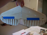
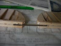
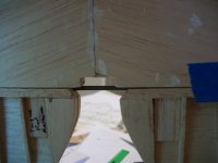
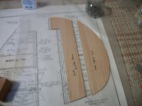
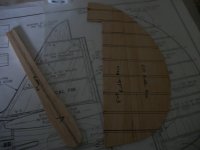
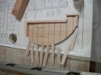
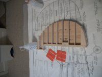
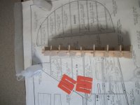
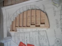
After consulting with my dad who has built 2 Top Flite warbirds his recommendation was to deviate from the plans when it came to the elevator counter balance blocks and shaping the LE of the elevators. It's easier to do the final sanding when the control surfaces hinged and taped flat (no shaping) than with the LE of the elevators shaped. I opted to wait until the I've gotten the rudder shaped and ready to hinge before hinging all of these control surfaces at the same time.


rcdude07
70cc twin V2
awesome work and pics...always exciting to see a kit build start to yield recognizable components of the airframe!
really enjoying watching this one, thanks for posting the updates.
Glad you are enjoying the thread. Balsa kit building is a dying art. I hope people are able to understand what it takes to get an ARF shipped to their door or LHS.
SnowDog
Moderator
Trust me, I've built a few balsa kits over the years...and I probably will again in the future...right now, I prefer to fly more than build, so yes, I truly do appreciate what it takes for that ARF to get to my door. I also appreciate the engineering that goes into building the ARFs from sticks of balsa into reliable, sturdy, reproducibly strong and square airframes.
