Ohio AV8TOR
Just Do It
Well my 60" Extreme Flight Edge came in and although this plane has been around for a while it still remains to be very popular and hopefully some things that I do or observe might ultimately help someone during their plane selection and or build.
First off my choice for this plane. I was flying a 47" 3DHS Extra SHP for my everyday flyer. My DA-60 87" Extra is for weekends but Capt Roll and myself both work at Nike Golf and it is real nice to fly every morning before work at our driving range. The 48" certainly fits the bill but after seeing the 60's fly they start to have that bigger plane feel that the 48" just don't have. I am progressing along with my 3D flying and am very comfortable with rollers right and left, not perfect but working on it. For me the slow flight characteristics of the 47" SHP is not that good. When I watch Capt Roll fly his 48" 3DHS Edge slow the Edge really comes through. So I looked at the 3DHS 58" Edge and the 60" Extreme Flight Edge. Hands down for me the looks of the Extreme Flight won me over. I love the Red, White, Blue and silver scheme and I really like the "T" version canopy for the 2-seater.
I considered the MXS-EXP again from all of the great feedback and because I like to tumble and it does it like no other. I will get the MXS some day but my choice was also based on the fact that so many says that the EF Edge is a great 3D trainer and I want to take my 3D flying down to the lower and slower and I believe this will do it.
I am a big fan of Motrolfly motors and have owned 3 of them so I was so happy to hear that the 4315 line was the way to go. Being I needed battery in the 4S or 6S size I went with the 6S because of the crazy power folks are getting with the -480kv wind and long 6-7 min flights.
I first would like to acknowledge the great feedback and ability to just talk over options with Gyro, cwojcik and rod.d here at 3DRC and also Chris (hercdriver7777), Aeroplayin, Tom K, Doc Austin and Daniel over at RCG. What an asset it is to glean the knowledge from those who have already been there. Thanks guys.
So my journey begins
So the plane arrived at my work address while we were still away on the Christmas break. When I returned I was so busy but I just had to break it out. First observation was the awesome packaging, everything had a place and everything was protected and no damage.
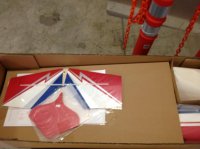
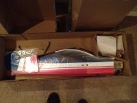
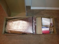
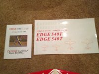
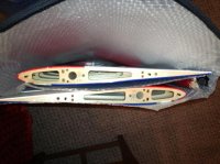
A couple of surprises and a few things that definitely put a smile on my face. The kit came with a nice lightweight spinner that is long like the Edge spinner. I had purchased a Great places aluminum back spinner before the kit arrived which I returned because this looks so much better. The graphics are plain but super quality and the packaging protected them as there are no folds or warps anywhere. And low and behold a printed manual (I thought those were extinct). Although my hopes are that I can get the plane in my FX35 with the wings on for quicker flying in the mornings the bags are actually nice and have a liner separation between the wing halves and does accommodate the wing tube.
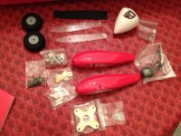
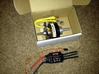
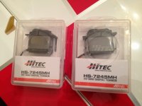
For the gear I have selected to finish this off is the MotrolFly 4315-480 with the ZTW B-Series ESC. My servos are HiTec HS-7245's and these will be my first plane with HV servos. I do have a Castle 10A BEC but at the moment I am planning on using a small 2S Lipo unregulated for servo power. I spoke with Mike Mayberry at HiTech about using unregulated because the servos say 7.4v and we all know that a 2S can be 8.4v fully charged. He assured me that the servos were rated for the battery nominal voltage and this was okay to do. I have plenty of 2S 450 lipos for my foamy and I also bought two 2S 800's to try. Many say they get 4 flight from a 450. From what I hear with the 4315-480 the plane balances correct with the battery right up to the wing tube. I will evaluate the slightly heavier 800's over the 450 based on balance point. The other advantage I see using the 800's over the 450's is the voltage will stay higher longer. That is one advantage of using an external BEC to maintain constant servo voltage and potentially a more contestant servo speed. This might be a work in progress for me.
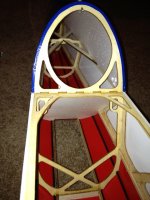
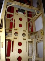
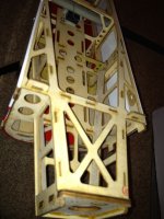
I mentioned earlier some thing put a smile on my face well how robust the the fuselage construction I really liked. Some planes make you feel like you need to hold them like a baby chick but this is not one of them. Great use of engineering the many support pieces and the use of triangle stock for re-enforcement's. This is something I always seem to find myself doing on other planes. I was also surprised and please to see the turtle deck lined with the foam balsa composite for strength and as you can see there are strong cross bracing across the back.
I went over all of these laser cut pieces with thin CA and suggest you do the same.
Another surprise was to see the slopped bulkhead that acts as a deflector for the existing cooling air passing through the fuselage. This is where I hit my first snag with the kit and I suggest you look at yours before cutting out the opening for the air. I proceded to cut this out using a Xacto knife heated and it all went well then when I passed a monokote iron over the edges to seal them I noticed that the bottom of this slopped bulkhead is not flush with the monokote surface of the fuselage bottom. At this point I am not really sure if a strip of wood is missing on mine that could have been added to provide a sealing surface. I was not happy that I did not see this because I can see the air from flying to blow back that covering on the bottom. What I did to fix this was to take some of the covering that I cut out and made a flap that I passed inside that slop wall and overlapped over the covering on the bottom. My suggestion to you would be to cut that covering away from that back wall by at least 1/2" and then wrap that inside the slopped wall to seal.
I used 15 minute epoxy to attach the control horns. Pretty straight forward but don't force fit the horn to the thin flat plate until you rough sand as they are a tight fit. You would not want to break that thin plate. It was nice that the ailerons already had the slot cut in them to accept the horn. Just drop the horn and plate in, mark with a pen and carefully (don't cut to deep) cut away the covering to epoxy. The aileron cutouts were also made for you. The runner and elevator do not have those slots pre-cut. One thing worthy of mentioning is they horns pressed in very nicelly and I did not have to work the holes out any.
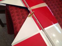
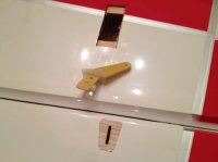
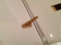
On to the hinging; Again pretty straight forward here but you do need to check carefully that the hinges are centered. None of mine were so I highly suggest that you remove each and place a small tick mark indicating the center line so when you attach the two halves you see this tick mark in the gap. This was a little tricky too and I found myself having to squeeze with my fingers on the pushing side so the hinge did not get pushed in. I actually had two that I could not get as they just tried to push all the way into one side. To remidy this I placed some thin CA on a piece of cardboard and touched an Xacto blade to this pool of CA to wick up so very slight amount of CA then touched the outermost edge of the hinge to tack it to the control surface. This worked good but you do not want to add CA until they are assembled.
I did not seal my gaps yet but plan on doing it. I normally use Blenderm but on this application I am going to try and find some 1/4" white trim tape and seal it with that.
Another smiling moment was looking at the massive elevator. 5-1/4" and with plenty of travel
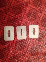
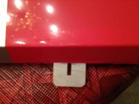
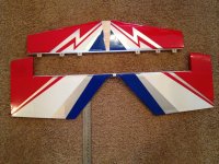
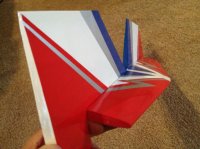
Cutting out the post support in the tail is pretty straight forward too. This reminded me when I built my first 48" Extreme Flight Extra. At first there was no mention of cutting that out in the manual and I went crazy trying to figure it out until an answer to my post came back. Some things I would mention is after you cut it out it mentions sanding it smooth. I recommend you wick in some thin CA first to stuffen up this piece. It is end grain and takes it nicely. Alos easy to over look but use a long tip on your thin CA bottle and add CA to that whole tail section inside to give you that piece of mind full throttle blenders.
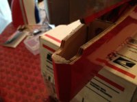
Mounted the stab assembly and I am very please with the alignment. No working of the cutout were necessary and the alignment with the wing tube was spot on. I slide the stab left and right to assure equal distance and then measured wing tube back to tips on both sides and kept repeating until all were equal.
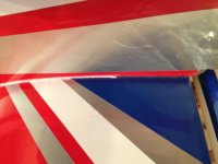
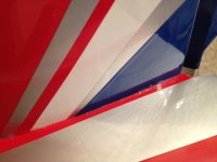
I used to run a Model Labs for consumer product development and here is tip that you may find useful. In this case I am using it to make a joint gap not only become more invisible but it adds strength too. You always get a few places that show more gap than we would like to see sometimes, like between the stab and fuse. Take some baking soda and CA to fix it. First apply the baking soda to fill the gap. Use you finger as a nice fillet tool and smooth out the baking soda to the fillet radius you want or even scrap it to a sharp corner with a straight edge. Use less finger pressure for a larger fillet radius and press harder for a small fillet radius. In this case I went for something that is about a 1mm radius fillet. Remember now this is just powder, if you don't like it blow it off and try again. What you see is what you will get so work it until you like it and wipe away any surrounding power not intended to cure. Then using a CA bottle with a tip hold it about 1/16" about the powder fillet and dispence one drop, you will see it wick more than you think. Move down and wick again. I like to tilt the part so the flow of CA is always in a controlled direction. Start on the high side and let gravity assist the wicking process. What you will see will amaze you because this white power not only becomes invisible it also takes on the color underneath out it so it will actually look like the trim lines matching. A couple of point to stress. Work it as a power until you like it because you can't change it once glued. Clean away any residual powder surrounding the fillet incase you drop more CA than you plan and use as little CA as you can dispense because it does not take much.
So one picture shows complete and the other half way done with the CA and you can see the color difference.
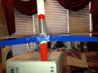
Awesome, I would be proud to take to the air with them and be an evangelist for the forum where ever I go. It's about Miller time for me (or chocolate milk time for Joe as we just found out he likes to drink) so with this talk of vinyl I went ahead and put on some to personalize it.
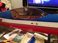
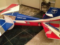
just love the look of the T model canopy. I guess I am partial to the Extra look so this just looks right to me. I do love the look of the straight leading edge of the Edge's wings so the best of both worlds for me.
Just realized how close the blue color is to my 87" Extra SHP so I can't wait to get a tandem picture at the field.
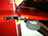
The tail wheel assembly was put together so nice and aligned I hated to take it apart but I like to grind on small flats for the grub screws so I did. If you have not done this simply dry assemble you parts and since down the grub screw and remove. This will leave a visual mark where you can grind a little flat. I like to use a dremel tool with either a cut off or flat grinder tool. Do not doe it all the way out the rod as the though here is if the screw loosens the assembly remains in tact.
Nothing hard her but you do need to ensure that the axle pivot is right on the rudder hinge line.
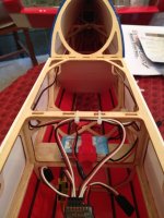
So now I moved to the elevator servo. The manual says to use a 24" extension which I had but after dry fitting everything I noticed that left me with quite a bit of excess so I went and bought 18" extensions. I don't know if the leads on the 7245 servos are extra long so check yours out first. Extreme flight took the time to add some slots on two of the aft bulkheads both right and left to accomodate the servo extensions to pass through and keep them secure during flight. I took that 24" extension and gravity fed it through the canopy side and down through both bulkhead slots. I then pulled that through the servo opening and connected it to my 18" extension and pulled it all through. I always like to secure my servo to extension connection with shrink tubing so I was worried it this would all pass through the slot and it did.
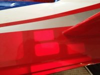
Cutting the opening can be tricky because there are several slots back there as shown in the picture below. I use a flashlight to shine from the opposite side which makes this much easier to see and work with. This is one of those measure twice cut once areas. Double check that you are in fact working with the intended surface and dry fit/place everything including control rods so there are no surprises.
One thing worth mentioning when installing servos that I see popping up from time to time - the brass tubes have a flange on one side, this side goes on the bottom or wood side. This flange prevents it from pushing in to the wood and also allows proper servo dampening from these rubber inserts. The servo screw have a washer size head and when tightening down you bottom out when the tube is tight not the rubber. When the tube is tight there is ample grommet dampening.
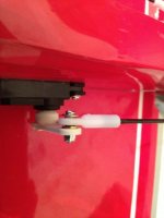
Another thing to always do when installing the ball links is to ensure that you use a washer on the screw head. This washer should be bigger than the ball diameter and is intended to keep this all an assembly if the ball decided to pop out of the plastic link.
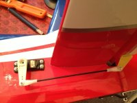
Yes I know the screw is missing for the servo control arm. During assemble I leave this off and I tape the control surface neutral, I then rotate the control arm to the neutral position and adjust the link length. When I get to the power on portion I remove these arms to allow servo centering without binding and then subtrim back to this neutral position.
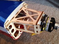
The Motrolfly 4315 motor requires a spacer to be used. I am using the optional light weight fiberglass mount from Ken and when I searched I found users were using either the 1/2" or 3/8" nylon standoffs that you can by at hardware or home type stores. They are cheep so I bought both. The canopy top ends before the fuselage sides do and when I had the 1/2" standoff it barley covered the canopy so I replaced them with the 3/8" which you see here. The cowl now overlaps the canopy by 1/4"
You will need some longer screws than the kit provided now that you are using these spacers and a word of caution to save you time, you need to install them through the fiberglass "before" you attach the fiberglass mount to the motor. THere is not enough clearance between the motor housing and the mount to slide the screw in otherwise.
I have had some problems this week with on going back pain and this was a bad week for me. So today I am hoping to get it finished.
I finished the connections for the Elevator and Rudder. I had to use the 24" extension after all on the rudder because the servo is most aft and the servo cable outlet is pointing back. So using the 18" on the elevator and the 24" on the rudder had them meet up real close at the receiver.
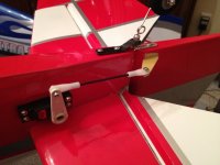
One thing using the long length DuBro servo arms is I found that I needed to place a washer also on the inside of the ball to space it out away from the DuBro arm to prevent binding. Remember to "always" put a washer on the screw head side so if the ball pops out of the link you still remain connected in flight.
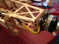
So on my 4315-480 installation as mentioned I ended up using 3/8" spacers so the cowl has a 1/4" overlap over the canopy. I mounted the ZTW 85A B-Series on the inside at the moment because so many I have talked to are running it under the battery tray to assist the balancing with using the 4315 motor. I found that to be a little hard using the ESC to battery lead length. Mounting it on the side like this provides an easy battery connection and it is actually still in the cowl air flow.
Please note that if you mount the motor with the leads coming out the side like you see here that you do need to pass a dremel over the ply side that extends. I just gave it a nice chamfer angle so the wires were not pinched.
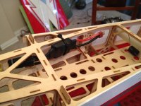
So now to the cowl. I always see some posts where this seems to be a problem for some to get the spinner gap and alignment right. I will share a technique that I have been doing for years and it is as close to fool proof as you can get and as you will see provides your desired gap and proper alignment.
For the cowl screw alignment holes I like to use strips of floder stock because the are stiffer than tape and always hinge back perfect. Make your pre alignment drill points for use to mark and drill. I always drill the first hole the screw pilot hole and later with the cowl off I drill the clearance hole in the cowl.
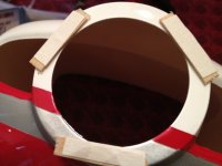
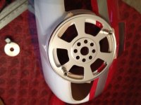
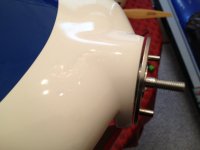
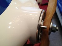
I like a tight spinner gap so I use these wood coffee stirrers that you can pick up free at your local coffee shop. We use double stick tape in the golf business for putting on grips but you can pick up carpet tape if you do not already have some. I snipped off three pieces of the sticks about 3/4-1" long and place the double stick tape on both sides of the wood. Remove the tape and stick them on the cowl to provide a nice offset surface the thickness you want. Use what ever thickness wood spacer you like to suit your preferred gap. I use three stick because a three legged stool always sits flat with no rocking. Then carefully place your spinner backplate onto the double stick tape. This controles everything so center it the best you can so the diameter of the cowl matches the diameter of your backplate. Then the rest is easy, simply slide on the cowl with the motor shaft going through the backplate and on over the fuselage. Secure your prop with the washer and nut finger tight to hold everything secure and drill your holes.
As you can see the results are as expected.
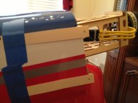
I should have added and mentioned how much I like a push-pull rudder setup. I forgot how easy they are to setup and have absolutely no slop. I am okay with the pull-pull on bigger planes but on the smaller planes they are just a PITA. Well done Extreme Flight
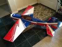
Well the back is about dead so I have to give it up for the day and go watch the play-off game. I have been listening to it on the radio and it sounds good. Should be no problem to finish it up later tonight or tomorrow. Hey at least it looks like a plane now. The SFG's have their vinyl on them and for now I will leave them off for simplicity. Everything is hooked up and moving in the right direction just need to set the throws, rates and balance the plane and then a once, twice, and a three times over.
For the throws I think I am going to set up triple rates and go pretty much per the manual having a low rate which I adjust later to suit my precision and roller rates. The middle rate will be my tradition 3D rate and the high rate will be the same 3D rates for the rudder and elevator but with the elevator like 80º or so to try some crazy stuff. I have not really tried that high of elevator rates but sounds fun to add for crazy tumbles, waterfalls and elevators.
One thing I will re-touch on that I really liked in this build is something that I picked up from hercdriver7777 (Chris Jewett) to setup your linkages first and you do this static without the radio on. So with power off and your control surfaces taped in the neutral position just place a straight edge along the hinge line to give you a closer view line to your control arm and push on (no screw needed) the control arm until absolutely parallel with the hinge line. I dropped the ball link screws in and adjust the length so the screws just drop in without moving the control arm. Screw the ball links on "and pull off" the servo control arms from the servo before you power them up. Power on the radio and receiver and then simply push back in as close to a spline as you can to get the control surface neutral and then subtrim that out for the surface to be neutral. Not a much different way of doing it but it was easy and I believe the travel both directions will be a lot closer.
So I have always used the Aero-Works throw meter for symmetrical surfaces because there is simply too much error in my opinion using any flat protractor against a curved surface. It works pretty good actually but you do need to prop up a taildragger to be more in level flight attitude to get full throws.
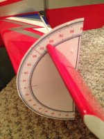
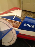
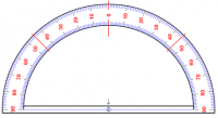
I saw something someone posted and I lost the link so I cannot give proper credit to them (sorry) for this. Very simple and costs basically nothing. Below is a file for a protractor that has been re-done to be used for RC. I brought this into Adobe Illustrator to have better control of the dimensions but with fiddling around in a graphics program you can scale this to suit your needed sizes. Anyway size one for each surface to read close to the numbers for the width of the control surface at the gap line. I spray mounted this printed paper to some folder stock to make it stiffer and I cut the protractor on that line close to the 90º dimensions. A little double stick tape on the back and place it in the gap against the fixed part of the plane and align the centerline and the "0" position to the control surface and you have a nice and easy way to set your surfaces. I will run this tomorrow and double check this with the throw meter. If you are on a budget or find this easier than what you are doing now have at it.
If someone knows who originally posted this protractor please let me know so I can give them credit here please.
First off my choice for this plane. I was flying a 47" 3DHS Extra SHP for my everyday flyer. My DA-60 87" Extra is for weekends but Capt Roll and myself both work at Nike Golf and it is real nice to fly every morning before work at our driving range. The 48" certainly fits the bill but after seeing the 60's fly they start to have that bigger plane feel that the 48" just don't have. I am progressing along with my 3D flying and am very comfortable with rollers right and left, not perfect but working on it. For me the slow flight characteristics of the 47" SHP is not that good. When I watch Capt Roll fly his 48" 3DHS Edge slow the Edge really comes through. So I looked at the 3DHS 58" Edge and the 60" Extreme Flight Edge. Hands down for me the looks of the Extreme Flight won me over. I love the Red, White, Blue and silver scheme and I really like the "T" version canopy for the 2-seater.
I considered the MXS-EXP again from all of the great feedback and because I like to tumble and it does it like no other. I will get the MXS some day but my choice was also based on the fact that so many says that the EF Edge is a great 3D trainer and I want to take my 3D flying down to the lower and slower and I believe this will do it.
I am a big fan of Motrolfly motors and have owned 3 of them so I was so happy to hear that the 4315 line was the way to go. Being I needed battery in the 4S or 6S size I went with the 6S because of the crazy power folks are getting with the -480kv wind and long 6-7 min flights.
I first would like to acknowledge the great feedback and ability to just talk over options with Gyro, cwojcik and rod.d here at 3DRC and also Chris (hercdriver7777), Aeroplayin, Tom K, Doc Austin and Daniel over at RCG. What an asset it is to glean the knowledge from those who have already been there. Thanks guys.
So my journey begins
So the plane arrived at my work address while we were still away on the Christmas break. When I returned I was so busy but I just had to break it out. First observation was the awesome packaging, everything had a place and everything was protected and no damage.


A couple of surprises and a few things that definitely put a smile on my face. The kit came with a nice lightweight spinner that is long like the Edge spinner. I had purchased a Great places aluminum back spinner before the kit arrived which I returned because this looks so much better. The graphics are plain but super quality and the packaging protected them as there are no folds or warps anywhere. And low and behold a printed manual (I thought those were extinct). Although my hopes are that I can get the plane in my FX35 with the wings on for quicker flying in the mornings the bags are actually nice and have a liner separation between the wing halves and does accommodate the wing tube.


For the gear I have selected to finish this off is the MotrolFly 4315-480 with the ZTW B-Series ESC. My servos are HiTec HS-7245's and these will be my first plane with HV servos. I do have a Castle 10A BEC but at the moment I am planning on using a small 2S Lipo unregulated for servo power. I spoke with Mike Mayberry at HiTech about using unregulated because the servos say 7.4v and we all know that a 2S can be 8.4v fully charged. He assured me that the servos were rated for the battery nominal voltage and this was okay to do. I have plenty of 2S 450 lipos for my foamy and I also bought two 2S 800's to try. Many say they get 4 flight from a 450. From what I hear with the 4315-480 the plane balances correct with the battery right up to the wing tube. I will evaluate the slightly heavier 800's over the 450 based on balance point. The other advantage I see using the 800's over the 450's is the voltage will stay higher longer. That is one advantage of using an external BEC to maintain constant servo voltage and potentially a more contestant servo speed. This might be a work in progress for me.


I mentioned earlier some thing put a smile on my face well how robust the the fuselage construction I really liked. Some planes make you feel like you need to hold them like a baby chick but this is not one of them. Great use of engineering the many support pieces and the use of triangle stock for re-enforcement's. This is something I always seem to find myself doing on other planes. I was also surprised and please to see the turtle deck lined with the foam balsa composite for strength and as you can see there are strong cross bracing across the back.
I went over all of these laser cut pieces with thin CA and suggest you do the same.
Another surprise was to see the slopped bulkhead that acts as a deflector for the existing cooling air passing through the fuselage. This is where I hit my first snag with the kit and I suggest you look at yours before cutting out the opening for the air. I proceded to cut this out using a Xacto knife heated and it all went well then when I passed a monokote iron over the edges to seal them I noticed that the bottom of this slopped bulkhead is not flush with the monokote surface of the fuselage bottom. At this point I am not really sure if a strip of wood is missing on mine that could have been added to provide a sealing surface. I was not happy that I did not see this because I can see the air from flying to blow back that covering on the bottom. What I did to fix this was to take some of the covering that I cut out and made a flap that I passed inside that slop wall and overlapped over the covering on the bottom. My suggestion to you would be to cut that covering away from that back wall by at least 1/2" and then wrap that inside the slopped wall to seal.


I used 15 minute epoxy to attach the control horns. Pretty straight forward but don't force fit the horn to the thin flat plate until you rough sand as they are a tight fit. You would not want to break that thin plate. It was nice that the ailerons already had the slot cut in them to accept the horn. Just drop the horn and plate in, mark with a pen and carefully (don't cut to deep) cut away the covering to epoxy. The aileron cutouts were also made for you. The runner and elevator do not have those slots pre-cut. One thing worthy of mentioning is they horns pressed in very nicelly and I did not have to work the holes out any.


On to the hinging; Again pretty straight forward here but you do need to check carefully that the hinges are centered. None of mine were so I highly suggest that you remove each and place a small tick mark indicating the center line so when you attach the two halves you see this tick mark in the gap. This was a little tricky too and I found myself having to squeeze with my fingers on the pushing side so the hinge did not get pushed in. I actually had two that I could not get as they just tried to push all the way into one side. To remidy this I placed some thin CA on a piece of cardboard and touched an Xacto blade to this pool of CA to wick up so very slight amount of CA then touched the outermost edge of the hinge to tack it to the control surface. This worked good but you do not want to add CA until they are assembled.
I did not seal my gaps yet but plan on doing it. I normally use Blenderm but on this application I am going to try and find some 1/4" white trim tape and seal it with that.
Another smiling moment was looking at the massive elevator. 5-1/4" and with plenty of travel


Cutting out the post support in the tail is pretty straight forward too. This reminded me when I built my first 48" Extreme Flight Extra. At first there was no mention of cutting that out in the manual and I went crazy trying to figure it out until an answer to my post came back. Some things I would mention is after you cut it out it mentions sanding it smooth. I recommend you wick in some thin CA first to stuffen up this piece. It is end grain and takes it nicely. Alos easy to over look but use a long tip on your thin CA bottle and add CA to that whole tail section inside to give you that piece of mind full throttle blenders.

Mounted the stab assembly and I am very please with the alignment. No working of the cutout were necessary and the alignment with the wing tube was spot on. I slide the stab left and right to assure equal distance and then measured wing tube back to tips on both sides and kept repeating until all were equal.
I used to run a Model Labs for consumer product development and here is tip that you may find useful. In this case I am using it to make a joint gap not only become more invisible but it adds strength too. You always get a few places that show more gap than we would like to see sometimes, like between the stab and fuse. Take some baking soda and CA to fix it. First apply the baking soda to fill the gap. Use you finger as a nice fillet tool and smooth out the baking soda to the fillet radius you want or even scrap it to a sharp corner with a straight edge. Use less finger pressure for a larger fillet radius and press harder for a small fillet radius. In this case I went for something that is about a 1mm radius fillet. Remember now this is just powder, if you don't like it blow it off and try again. What you see is what you will get so work it until you like it and wipe away any surrounding power not intended to cure. Then using a CA bottle with a tip hold it about 1/16" about the powder fillet and dispence one drop, you will see it wick more than you think. Move down and wick again. I like to tilt the part so the flow of CA is always in a controlled direction. Start on the high side and let gravity assist the wicking process. What you will see will amaze you because this white power not only becomes invisible it also takes on the color underneath out it so it will actually look like the trim lines matching. A couple of point to stress. Work it as a power until you like it because you can't change it once glued. Clean away any residual powder surrounding the fillet incase you drop more CA than you plan and use as little CA as you can dispense because it does not take much.
So one picture shows complete and the other half way done with the CA and you can see the color difference.


... And yes, Ray will get some Vinyl for his airplane from us
Awesome, I would be proud to take to the air with them and be an evangelist for the forum where ever I go. It's about Miller time for me (or chocolate milk time for Joe as we just found out he likes to drink) so with this talk of vinyl I went ahead and put on some to personalize it.

just love the look of the T model canopy. I guess I am partial to the Extra look so this just looks right to me. I do love the look of the straight leading edge of the Edge's wings so the best of both worlds for me.
Just realized how close the blue color is to my 87" Extra SHP so I can't wait to get a tandem picture at the field.
The tail wheel assembly was put together so nice and aligned I hated to take it apart but I like to grind on small flats for the grub screws so I did. If you have not done this simply dry assemble you parts and since down the grub screw and remove. This will leave a visual mark where you can grind a little flat. I like to use a dremel tool with either a cut off or flat grinder tool. Do not doe it all the way out the rod as the though here is if the screw loosens the assembly remains in tact.
Nothing hard her but you do need to ensure that the axle pivot is right on the rudder hinge line.

So now I moved to the elevator servo. The manual says to use a 24" extension which I had but after dry fitting everything I noticed that left me with quite a bit of excess so I went and bought 18" extensions. I don't know if the leads on the 7245 servos are extra long so check yours out first. Extreme flight took the time to add some slots on two of the aft bulkheads both right and left to accomodate the servo extensions to pass through and keep them secure during flight. I took that 24" extension and gravity fed it through the canopy side and down through both bulkhead slots. I then pulled that through the servo opening and connected it to my 18" extension and pulled it all through. I always like to secure my servo to extension connection with shrink tubing so I was worried it this would all pass through the slot and it did.
Cutting the opening can be tricky because there are several slots back there as shown in the picture below. I use a flashlight to shine from the opposite side which makes this much easier to see and work with. This is one of those measure twice cut once areas. Double check that you are in fact working with the intended surface and dry fit/place everything including control rods so there are no surprises.
One thing worth mentioning when installing servos that I see popping up from time to time - the brass tubes have a flange on one side, this side goes on the bottom or wood side. This flange prevents it from pushing in to the wood and also allows proper servo dampening from these rubber inserts. The servo screw have a washer size head and when tightening down you bottom out when the tube is tight not the rubber. When the tube is tight there is ample grommet dampening.
Another thing to always do when installing the ball links is to ensure that you use a washer on the screw head. This washer should be bigger than the ball diameter and is intended to keep this all an assembly if the ball decided to pop out of the plastic link.
Yes I know the screw is missing for the servo control arm. During assemble I leave this off and I tape the control surface neutral, I then rotate the control arm to the neutral position and adjust the link length. When I get to the power on portion I remove these arms to allow servo centering without binding and then subtrim back to this neutral position.


The Motrolfly 4315 motor requires a spacer to be used. I am using the optional light weight fiberglass mount from Ken and when I searched I found users were using either the 1/2" or 3/8" nylon standoffs that you can by at hardware or home type stores. They are cheep so I bought both. The canopy top ends before the fuselage sides do and when I had the 1/2" standoff it barley covered the canopy so I replaced them with the 3/8" which you see here. The cowl now overlaps the canopy by 1/4"
You will need some longer screws than the kit provided now that you are using these spacers and a word of caution to save you time, you need to install them through the fiberglass "before" you attach the fiberglass mount to the motor. THere is not enough clearance between the motor housing and the mount to slide the screw in otherwise.

I have had some problems this week with on going back pain and this was a bad week for me. So today I am hoping to get it finished.
I finished the connections for the Elevator and Rudder. I had to use the 24" extension after all on the rudder because the servo is most aft and the servo cable outlet is pointing back. So using the 18" on the elevator and the 24" on the rudder had them meet up real close at the receiver.
One thing using the long length DuBro servo arms is I found that I needed to place a washer also on the inside of the ball to space it out away from the DuBro arm to prevent binding. Remember to "always" put a washer on the screw head side so if the ball pops out of the link you still remain connected in flight.


So on my 4315-480 installation as mentioned I ended up using 3/8" spacers so the cowl has a 1/4" overlap over the canopy. I mounted the ZTW 85A B-Series on the inside at the moment because so many I have talked to are running it under the battery tray to assist the balancing with using the 4315 motor. I found that to be a little hard using the ESC to battery lead length. Mounting it on the side like this provides an easy battery connection and it is actually still in the cowl air flow.
Please note that if you mount the motor with the leads coming out the side like you see here that you do need to pass a dremel over the ply side that extends. I just gave it a nice chamfer angle so the wires were not pinched.


So now to the cowl. I always see some posts where this seems to be a problem for some to get the spinner gap and alignment right. I will share a technique that I have been doing for years and it is as close to fool proof as you can get and as you will see provides your desired gap and proper alignment.
For the cowl screw alignment holes I like to use strips of floder stock because the are stiffer than tape and always hinge back perfect. Make your pre alignment drill points for use to mark and drill. I always drill the first hole the screw pilot hole and later with the cowl off I drill the clearance hole in the cowl.
I like a tight spinner gap so I use these wood coffee stirrers that you can pick up free at your local coffee shop. We use double stick tape in the golf business for putting on grips but you can pick up carpet tape if you do not already have some. I snipped off three pieces of the sticks about 3/4-1" long and place the double stick tape on both sides of the wood. Remove the tape and stick them on the cowl to provide a nice offset surface the thickness you want. Use what ever thickness wood spacer you like to suit your preferred gap. I use three stick because a three legged stool always sits flat with no rocking. Then carefully place your spinner backplate onto the double stick tape. This controles everything so center it the best you can so the diameter of the cowl matches the diameter of your backplate. Then the rest is easy, simply slide on the cowl with the motor shaft going through the backplate and on over the fuselage. Secure your prop with the washer and nut finger tight to hold everything secure and drill your holes.
As you can see the results are as expected.


I should have added and mentioned how much I like a push-pull rudder setup. I forgot how easy they are to setup and have absolutely no slop. I am okay with the pull-pull on bigger planes but on the smaller planes they are just a PITA. Well done Extreme Flight

Well the back is about dead so I have to give it up for the day and go watch the play-off game. I have been listening to it on the radio and it sounds good. Should be no problem to finish it up later tonight or tomorrow. Hey at least it looks like a plane now. The SFG's have their vinyl on them and for now I will leave them off for simplicity. Everything is hooked up and moving in the right direction just need to set the throws, rates and balance the plane and then a once, twice, and a three times over.
For the throws I think I am going to set up triple rates and go pretty much per the manual having a low rate which I adjust later to suit my precision and roller rates. The middle rate will be my tradition 3D rate and the high rate will be the same 3D rates for the rudder and elevator but with the elevator like 80º or so to try some crazy stuff. I have not really tried that high of elevator rates but sounds fun to add for crazy tumbles, waterfalls and elevators.
One thing I will re-touch on that I really liked in this build is something that I picked up from hercdriver7777 (Chris Jewett) to setup your linkages first and you do this static without the radio on. So with power off and your control surfaces taped in the neutral position just place a straight edge along the hinge line to give you a closer view line to your control arm and push on (no screw needed) the control arm until absolutely parallel with the hinge line. I dropped the ball link screws in and adjust the length so the screws just drop in without moving the control arm. Screw the ball links on "and pull off" the servo control arms from the servo before you power them up. Power on the radio and receiver and then simply push back in as close to a spline as you can to get the control surface neutral and then subtrim that out for the surface to be neutral. Not a much different way of doing it but it was easy and I believe the travel both directions will be a lot closer.

So I have always used the Aero-Works throw meter for symmetrical surfaces because there is simply too much error in my opinion using any flat protractor against a curved surface. It works pretty good actually but you do need to prop up a taildragger to be more in level flight attitude to get full throws.
I saw something someone posted and I lost the link so I cannot give proper credit to them (sorry) for this. Very simple and costs basically nothing. Below is a file for a protractor that has been re-done to be used for RC. I brought this into Adobe Illustrator to have better control of the dimensions but with fiddling around in a graphics program you can scale this to suit your needed sizes. Anyway size one for each surface to read close to the numbers for the width of the control surface at the gap line. I spray mounted this printed paper to some folder stock to make it stiffer and I cut the protractor on that line close to the 90º dimensions. A little double stick tape on the back and place it in the gap against the fixed part of the plane and align the centerline and the "0" position to the control surface and you have a nice and easy way to set your surfaces. I will run this tomorrow and double check this with the throw meter. If you are on a budget or find this easier than what you are doing now have at it.
If someone knows who originally posted this protractor please let me know so I can give them credit here please.


