Alky6
150cc
Elevators:
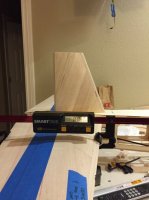
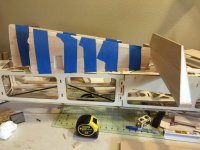
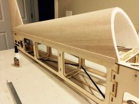
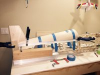
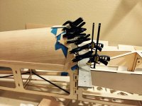
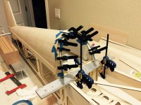
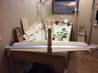
To ensure the elevators get cut correctly (and perpendicular to the centerline of the fuse) I used a 4' straight edge centered and measured to a point at the centerline of of F1. During the process, I realized that the 6-32 screws to hold on the stabs were a wee bit too small and there is slop in the mounting. Didn't notice before when I set the incidence as I had the stab tube tight in the sockets. Will have to get that done before I cut out the elevators, but I now have a nice known perpendicular line to reference off of.
Rudder:
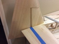
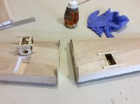
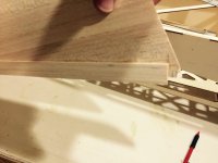
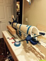
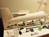
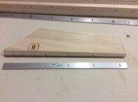
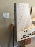
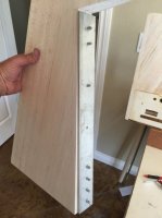
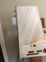
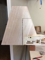
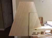
Used a piece of alluminum bar stock to use as a template for the hinge holes. Added extra hinges at the bottom of the rudder because I am only going to use one servo (push-pull) which I gather will add a bit more hinge loading in this area. Also started beveling the surfaces. One interesting point for those that have never done it on a tapered surface, you can't simply draw a line at equal depths along the LE and TE pieces. Using the largest width of the rudder I used similar triangles to determine the depth so I have a line to work to when shaping and sanding the LE and TE.


