• If you are new to GiantScaleNews.com, please register, introduce yourself, and make yourself at home.

    We're 1st in Giant Scale RC because we've got the best membership on the internet! Take a look around and don't forget to register to get all of the benefits of GSN membership!

    Welcome!

Krill Extra 330 LX building thread

TazmanianDevil

Xtreme by DeFinition !
Hey @TazmanianDevil,

What's the little black device to the left of your Smartfly board in the top picture on this page?

You're doing an awesome job on an incredible airplane. . . . . :yesss: Keep up the great work.
It's the DC UP mk2 by Fromeco. Actually it's a DCup and a Cricket combined.
The DCup has 4 capacitors that holds well enough energy if I'll have a blow back in the system like a voltage drop.
The LED scale let me know what was the lowest voltage in a flight.
Keeps me monitoring the batteries and the system function.
ImageUploadedByTapatalk1448549133.049498.jpg
ImageUploadedByTapatalk1448549162.595250.jpg
ImageUploadedByTapatalk1448549206.884225.jpg
 

TazmanianDevil

Xtreme by DeFinition !
Final touch before the engine and canisters.
What I've been trying to do is to make it as simple as possible so the entire engine components will be on the fuel tank tray.
The battery the ignition cut off and more.
No cutting through the fuse at all with no fuel dots switches and all. Everything is inside the fuse.
What I could put through the fuse tray I did and what I didn't want I just hanged it with Velcro for inspection and to see that everything is ok before the flights.

The ignition is mounted inside the fuse. Not like the SU 29 where you have a lot of room because of the cowl here there is no such thing so I've mounted it in side with 3 screws and nylook bolts the brackets are built in with the ignition.

There for hols are being made for the ignition shoes sensor and fuel hose.
I've got the fuel line ignition cable and sensor from the same hole.
Of course all hols in a composite frame must be installed with rubber grummets.

Last but not least, the antenna tower a simple V shape balsa covered with heat shrink.

Now I'll wait for the engine with the canisters to arrive from CZ.
ImageUploadedByTapatalk1448874739.282006.jpg
ImageUploadedByTapatalk1448874749.651071.jpg
ImageUploadedByTapatalk1448874760.006310.jpg
ImageUploadedByTapatalk1448874770.142101.jpg
ImageUploadedByTapatalk1448874779.582909.jpg
ImageUploadedByTapatalk1448874788.871078.jpg
ImageUploadedByTapatalk1448874797.525035.jpg
ImageUploadedByTapatalk1448874806.428330.jpg
ImageUploadedByTapatalk1448874815.401047.jpg
ImageUploadedByTapatalk1448874824.122007.jpg
ImageUploadedByTapatalk1448874833.826713.jpg
ImageUploadedByTapatalk1448874843.717581.jpg
ImageUploadedByTapatalk1448874875.998086.jpg
ImageUploadedByTapatalk1448874885.240366.jpg
ImageUploadedByTapatalk1448874894.974299.jpg
ImageUploadedByTapatalk1448874904.062219.jpg
ImageUploadedByTapatalk1448874912.951933.jpg
 
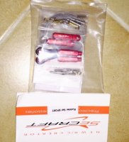
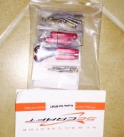
Could you tell me, please, the width of the part that has the pin in it on these Secraft rudder pieces? In other words, what is the width between control horns on the rudder?
 

Attachments

  • Capture5.JPG
    Capture5.JPG
    51.1 KB · Views: 417
The bellcrank is 5" and the horn width is 5" as well.
Thank you, but I am asking about the little red piece that attaches to the control horn on the rudder. The one that has a pin to hold it on and fits between the control horn pieces you installed. See where I drew a line?
 

Attachments

  • measure.JPG
    measure.JPG
    74.9 KB · Views: 416

HRRC Flyer

GSN Sponsor Tier 1
Hello @TazmanianDevil,

Thank you for your response to my last question. I hope you don't get tired of all my questions, but I have another. I am not sure how to ask this without it sounding like criticism, which is the furthest from my intent. Anyway, why did you not use double arms on your rudder servos and connect to both sides of the rudder bell crank?

Thanks
 

TazmanianDevil

Xtreme by DeFinition !
Im here to answer questions so you can ask them all day long

That's something I was thinking about for a long time now.
Before there where high end cnc made bellcranks there was just the servo with full arm, cables where attached to it and a line of 2-3 servos where aligned in series on his back...All where with full arm so they will be able to support the first servo, from all the stress and tension the cables and surface are making.
That method continued even though pilots used high end bellcrank for the rudder.

I just did what everyone afraid to do or just didn't want to do because of maybe tradition.
Im using 1" arm so I'm able to get full 888 oz/in, on that specific bellcrank I have an offset of about 1.5" so I reckon there will be a lost of about 50% power. That will be tolerable considering I'm flying IMAC and the top the surface will move for the most will be 40 degrees when I land.
There is no mathematical benefit using full arm with high end bellcrank (the force and torque are divided )
When you use a Push Pull system it's the same.
Again it applies when you're using high end bellcrank.

Just my 2c.
 
Last edited:
Top