GSNadmin
Staff member
With many of today’s giant scale aerobatic aircraft multiple servos are often used to move each flight control surface. Modern computer radios actually have specialized menus to help setup and adjust multi-servo installations, but you can do it the old fashion way as well by using programmable mixes. Basically you setup a two servo setup (for ailerons for example,) and then you mix the left and right servo channels to two other auxiliary channels ending up with two servos controlling each aileron surface.

But to fine tune you setup, you need to make sure that all of the servos attached to the same control surface don’t fight against each other. You do this by first carefully adjusting each servo’s end points and the center positions until the two aileron servos move in unison. You can check for a proper setup by reading each servo’s current draw.


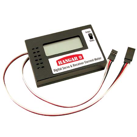
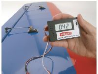
To do this, you can use a “Digital Servo and a Current Meter” from Hangar 9. Reading the actual servo draw you can find easily find mismatched servos and binding linkages.

Another way to measure servo current is to use a common digital multi-meter. But first you’ll need a way to connect the meter between the servo and the receiver. To do this you’ll need: a set of test probes (that plug into the multi-meter), a soldering iron and solder, wire cutters, a wire stripper, heat-shrink tubing, and a 12-inch heavy-duty servo extension.

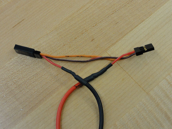
Here’s how I made my patch harness.
1. Cut the power red wire on a 12-inch heavy-duty servo extension and strip back both ends of the wire approximately 1/8-inch.
2. Clip off the test probe from each wire and strip back both wires approximately 1/8-inch and tin all the wires.
3. Solder the red power line on the female connector to the black ground test probe wire that will plug into the multi-meter. Use heat-shrink tubing to cover the solder joint.
4. Solder the red power line on the male connector to the red power test probe wire that will plug into the multi-meter, again covering the solder joint with heat-shrink tubing.
5. Turn the multi-meter on and select the proper current setting.
6. Plug the servo into the female connector of our custom harness and plug the male connector of our custom harness into the correct port on the receiver.
7. Power on both the transmitter and aircraft and see the current draw. Make any necessary changes in the linkage setup to decrease it. Ideally, this number would be as close to zero as possible.
Model Airplane News - The #1 resource for RC plane and helicopter enthusiasts featuring news, videos, product releases and tech tips.
Continue reading...

But to fine tune you setup, you need to make sure that all of the servos attached to the same control surface don’t fight against each other. You do this by first carefully adjusting each servo’s end points and the center positions until the two aileron servos move in unison. You can check for a proper setup by reading each servo’s current draw.


To do this, you can use a “Digital Servo and a Current Meter” from Hangar 9. Reading the actual servo draw you can find easily find mismatched servos and binding linkages.

Another way to measure servo current is to use a common digital multi-meter. But first you’ll need a way to connect the meter between the servo and the receiver. To do this you’ll need: a set of test probes (that plug into the multi-meter), a soldering iron and solder, wire cutters, a wire stripper, heat-shrink tubing, and a 12-inch heavy-duty servo extension.

Here’s how I made my patch harness.
1. Cut the power red wire on a 12-inch heavy-duty servo extension and strip back both ends of the wire approximately 1/8-inch.
2. Clip off the test probe from each wire and strip back both wires approximately 1/8-inch and tin all the wires.
3. Solder the red power line on the female connector to the black ground test probe wire that will plug into the multi-meter. Use heat-shrink tubing to cover the solder joint.
4. Solder the red power line on the male connector to the red power test probe wire that will plug into the multi-meter, again covering the solder joint with heat-shrink tubing.
5. Turn the multi-meter on and select the proper current setting.
6. Plug the servo into the female connector of our custom harness and plug the male connector of our custom harness into the correct port on the receiver.
7. Power on both the transmitter and aircraft and see the current draw. Make any necessary changes in the linkage setup to decrease it. Ideally, this number would be as close to zero as possible.
Model Airplane News - The #1 resource for RC plane and helicopter enthusiasts featuring news, videos, product releases and tech tips.
Continue reading...
