• If you are new to GiantScaleNews.com, please register, introduce yourself, and make yourself at home.

    We're 1st in Giant Scale RC because we've got the best membership on the internet! Take a look around and don't forget to register to get all of the benefits of GSN membership!

    Welcome!

Official 3drcf build and review - lightrc.com 35" rebel z

Bipenut53

150cc
Hello all!! I am going to build the Light RC 35" Rebel Z foamie airplane here in this log. First off I need to thank 3DRCForums.com, RCFoamies.com, LightRC.com, and [MENTION=2643]3DMIKE[/MENTION] for this opportunity to build this airplane.

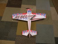
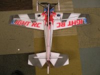
The Rebel Z is a Light RC exclusive design, mixing attributes from several classic aircraft. The Rebel Z is a blend of the Acro, Laser, Rebel and variants of these. Using carbon to stiffen the chassis much like an indoor plane would. This stiff airframe allows the plane to fly better, as well as handle more wind, and challenge your 3D skills. This design is the most extreme flying model Light RC is currently offering.

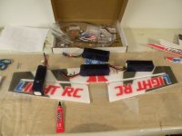
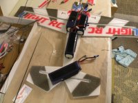
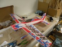
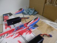
I opened the box and this is the way the airplane comes:
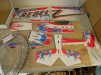
DSCN3033.JPG


These are the electrics I got with this airplane:

1 Turnigy 3020-1800 brushless motor
4 Li-Power 9g servos
2 Rhino 610 mah 3 cell 20c lipo batteries
1 Guard 20 amp ESC
4 2" servo extensions

I will be adding a mini receiver for Spektrum
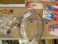
DSCN3035.JPG

So I will get started and update as I go
 
Last edited by a moderator:

Bipenut53

150cc
I got some time to build on this bird, so here is what I got done. In this build I am going to use Welders adhesive, a small amount of CA, and a small amount of hot glue.

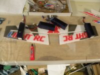
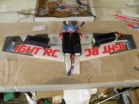
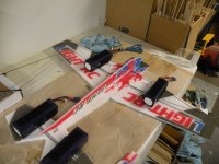
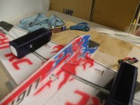
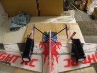
I started out by gluing the wings to the nose third of the fuselage.I used some 5000 mah 6 cell batteries to keep everything flat on my building table to ensure a straight wing.

DSCN3039.JPG


After the Welders set long enough, I cut to length the 6mm main wing spar and glued it in place.


DSCN3040.JPG


I then cut the 3mm second wing spar and glued it in place. One thing I should mention here is I always dry fit everything. In the process of doing that I found the slots for the spars still had some foam that was hanging on in the slots. I used the blunt side of a razor blade and ran through the slots for a better fit. After I got the second spar glued in I then glued the second third of the fuse to the back of the second wing spar. It seems to me to be important to wait to glue the whole fuse together at once because the glue joint for the second spar would get glued shut.

DSCN3044.JPG


More to come very soon!!
 
Last edited by a moderator:
Bipenut53

150cc
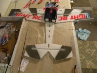
Ok so after gluing in the spars on the wing I let the assembly dry overnight and removed from the table and re-positioned it so I could glue the rest of the horizontal fuse together

DSCN3047.JPG


I then added the elevator 3mm carbon piece in and used the 6 cell batteries again to keep everything flat while it dried.

DSCN3048.JPG


The vertical upper and lower fuse comes in 2 pieces for the top and 2 pieces for the bottom for shipping purposes. I glued the halves together so I ended up with an upper vertical fuse that included the rudder and the lower fuse halves together, all of this to get ready for the next steps.

DSCN3049.JPGDSCN3050.JPGDSCN3051.JPG


At that point I let everything sit over night to dry completely. The next step is to glue the lower fuse half to the horizontal fuse. It is important when gluing the lower fuse on that it is square to the horizontal. I used one of my triangles I have for building to ensure the lower fuse was square the whole length of the fuse.

DSCN3052.JPGDSCN3053.JPG


As you can see in the second picture the triangle is against the lower fuse and the horizontal fuse. I checked this many times on both sides. Wow it is starting to really look like something!! I will allow this assembly to dry. More to come!!
 
Last edited by a moderator:
Bipenut53

150cc
So after enough time has passed and the glue has enough time to set pretty good I added the gear legs


DSCN3054.JPG


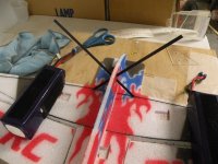
I then cut the 1mm carbon rods to the correct length and installed them as per manual while keeping the lower fuse square to the horizontal fuse assembly


DSCN3055.JPGDSCN3056.JPG


I then added the plastic runners on the bottom of the foam wheels


DSCN3057.JPG


And then glued the wheels to the bottom of the gear legs


DSCN3058.JPGDSCN3059.JPG


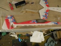
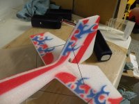
At that point I was ready to put the airplane upright and add the upper vertical fuse to the horizontal assembly. This is a little tricky because the rudder wraps around the elevator and glues on the bottom. I added the upper fuse and I chose to pin the lower vertical to the upper vertical at the rudder to keep everything straight while drying.... Now we have an airplane!!


DSCN3060.JPG


More to come very soon!!!!
 
Last edited by a moderator:
Bipenut53

150cc
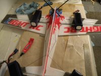
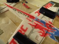
Ok so I am going to finish up the build. After I glued the top vertical fuse in place I let the assembly dry and made sure everything was square. I then added the tail skid

DSCN3061.JPG


Then I had to add the remaining 1mm carbon tail supports

DSCN3062.JPG

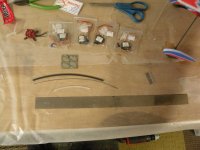
I got the motor, ESC, servos, control horns, and control rods out and sorted. You have to cut the wire for z bends at the ends of the control rods and that is as easy as cutting the wire into 8 equal lengths and take a small pair of needle nose pliers and put the z bend in.

DSCN3063.JPG

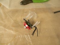
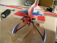
At that point I decided I would start with the motor mount. This is a unique simple setup. You take the supplied rigid white plastic tube and cut it into 4 equal lengths, use the supplied 4 Phillips head screws and loosely put them on the motor.

DSCN3064.JPG


I then soldered the bullet connectors on the motor and ESC. I used hot glue to mount the motor to the fuse. That is done by putting the motor on the nose and rotating the mount clockwise as you look at the nose, that puts the plastic tubes laying flat on each part of the fuse, meaning on the verticals and horizontals so that when the motor spins the prop, the torque of the motor presses against the fuse and not trying to pull the mounts away from the fuse. It is far easier done than said!


DSCN3067.JPG


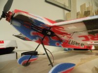
I then measured where the CG is supposed to start out, 8 inches from the nose of the airplane (foam part). I put a dot on the fuse to aid me while I found a suitable location for the ESC, once I found the best place I hot glued the ESC to the fuse.

DSCN3068.JPG


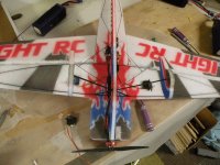
I then hot glued the servos into their pockets in the wing and horizontal fuse for the elevator. The rudder servo glues right behind the elevator servo on the vertical fuse. I used welders glue to glue the control horns into place. Take note these are all the same except the elevator control horn has a cut out for the carbon fiber elevator spar.

DSCN3069.JPG


I double back taped the receiver to the vertical fuse, used a zip tie to bundle the servo wires to make a neat and clean install and hot glued them in place where the vertical and horizontal fuse meet on the underside of the airplane.


DSCN3075.JPG


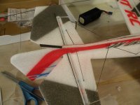
I used T-pins to hold the control surfaces in their neutral position

DSCN3070.JPGDSCN3071.JPG


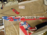
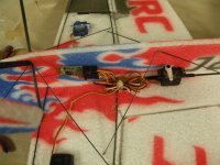
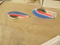
I then cut the heat shrink, now this is cool heat shrink, it has glue that is heat activated so no need to CA and heat the heat shrink. I cut the control rods to length, put the z bend wires on the servos and control horns, slid the heat shrink over the z bends and when I was happy with the position I heated them with a lighter. Works perfect!!!

I am going to put the battery on top of the fuse with Velcro so it will be easy to fine tune the CG when I maiden the airplane. This concludes the build portion of the Rebel Z

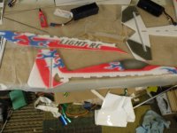
DSCN3072.JPGDSCN3073.JPGDSCN3074.JPGDSCN3076.JPG
 
Last edited by a moderator:
Bipenut53

150cc
Light RC 35" Rebel Z maiden is done and here is the review.
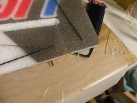
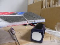
It is EPP Foam construction with carbon fiber rods for stiffeners, carbon fiber control linkages, carbon fiber landing gear, 2 carbon fiber spars in the wing with carbon fiber stiffeners on the aileron counterbalance. Also there is a carbon fiber spar in the leading edge of the elevator. This all makes for a very rigid foamy airplane that flys a lot like a balsa model with no flexing you can get with an EPP airplane of this size without all of the CF. It is a very responsive airplane and will do more than I am capable of doing. Knife edge flight is a dream as with any flat foamy airplane. I was afraid that with the first harder than normal landing that the CF stiffener rods would start popping off. I am very happy to report that I hit the floor pretty hard a few times on the indoor portion of the flying and none of the CF rods popped off or even moved in any way. The motor supplied with the airplane was on the small side and I will be upgrading it very soon as the motor got very warm while testing and pretty warm when flying. The outdoor portion of the flying was done with a 8x4.3 SF prop, too much for this motor. The indoor portion of the flying was done with a 7.4 SF prop and the motor was happier with that. The motor would barely hang in a hover which will be much better with a better motor. Harrier flying is a breeze with very little to no wing rock at very slow speeds. The roll rate is blinding fast if used at full deflection, and quite manageable when in rolling harrier flight. Before I got the plane out for its maiden the servo on the left aileron failed, so I had to remove it from the wing, I was very afraid that the EPP foam would tear while separating the servo from the wing because the pocket that the servo set in made the foam very thin at that point. But the foam is very resilient and did not tear one bit!
I believe this is a great little airplane that will handle light to moderate wind (5-10 mph), and is not too big to fly indoors! This kit is not for a beginner to build, but if you have built one or two foamy airplanes you will be able to handle it with no problem at all. It is truly a fun airplane to fly indoors and outdoors!


[video=youtube;JBxq4WU1jF4]https://www.youtube.com/watch?v=JBxq4WU1jF4[/video]
 
Last edited by a moderator:
Top