cwojcik
70cc twin V2
Before I start, let me just say that the methods I describe in here are what work for me and make the most sense to me. There is more than one answer to most technical questions, so I’m not saying that the methods I describe are the only way to do things. If you take issue with what I am saying then please, let me know why!
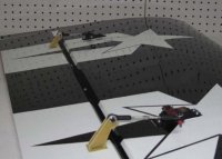
One of the most daunting (and important) tasks in setting up a giant scale airplane is setting up ganged servos (multiple servos on one surface). The challenge is in synchronizing the movements of the servos so that they do not fight each other, leading to undue stresses, servo wear, and battery use. Depending on your choice of servos, transmitter/receiver, and power distribution system (Power Expander, PowerBox, etc), you will have several options.
Options
The first option, and my favorite, is to use your transmitter to match your servos. If you have, for example, a 9 channel radio and a 100cc airplane with two servos per aileron, one per elevator, and one on the rudder, then you have enough channels to simply plug every servo into a unique port, and use the programming in the radio to match the servos. It should be noted that the 9303 and 9503, even though they have enough channels, lack the programming capability to do this.
The second option is to use a power distribution system that has built-in servo matching, such as the Smart-Fly PowerExpander EQ10. When you install your receiver in a system such as this, each channel from your receiver controls more than one port on the power expander. You can then program custom endpoints and center points on the power expander itself for each individual port. There are other power expander systems like the PowerExpander Pro that give the same signal on multiple ports and do not allow you to program the output of each individual port.
The third option is to use a matching device like a JR Matchbox or Smart-Fly Equalizer. These devices are similar to a Y-harness in that they take one input and split it into two or more outputs. However, each output can be programmed individually. They also usually have provisions for providing separate power to the servos plugged into them, so you don’t have to worry about pulling two or three servos worth of current through one plug. I haven’t used one of these devices yet so I won’t explain how to use it, but the mechanical set-up section still applies here.
The fourth option is the lightest, simplest, and cheapest, but the most cumbersome to set up: programming each servo directly. Some digital servos, such as Hitec, can be individually programmed to have custom center and endpoints. You can send each servo the same position signal and each servo will go to a custom programmed position. If you are using a power expander without built-in servo matching or a matching device like an equalizer or matchbox and you have more servos than channels, this is probably the only way to go.
Mechanical Set-Up
First, let’s look at mechanical set-up. Doing this properly will make much less work for you later during the electronic set-up, and in some cases, electronic matching will not be able to overcome poor mechanical set-up.
Good mechanical set-up mainly means two things. First, you are getting the proper amount of throw for a given amount of servo travel. If your servo arms are longer than they should be (or your control surface horns are too short), you will probably run your surfaces into the bevels before you reach 100% movement on the servo. This means you are putting undue stress on the servos and losing out on power and resolution. Conversely, if your arms are too short or your surface horns are too long, you will not get enough throw no matter what. This applies to all aircraft, even those without ganged servos.
Secondly, good mechanical set-up means that the surfaces are achieving equal throw in both directions with equal servo movement. If the pivot point on your control surface horns is directly over the hinge line, this will be achieved by having the servo arm parallel to the hinge line. If you have horns that place the pivot point further back (over the surface, rather than the hinge line), then that’s OK too. This is usually the case with older rocket-city style adjustable horns, and we can accommodate for them. To achieve this second goal, you should first assemble the linkage on the control surface. If the pivot points for your horns are over the hinge line, then adjust the pushrod length by turning the turnbuckle until the servo arm is parallel with the hinge line…you’re done.
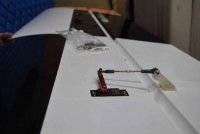
If it’s not, then you can measure the movement of the servo arm with a protractor as you also measure the movement of the surface. Adjust the length of the pushrod until the movement of the servo is equal on either side of neutral for equal control surface movement on either side of neutral. IE, if the servo must move 50 degrees in one direction for the surface to achieve 40 degrees of movement up, the servo should also need to move 50 degrees in the opposite direction to achieve 40 degrees of control surface movement down. Am I making any sense? You can also test this by using a servo tester or your transmitter instead of a protractor on your servo. 100% ATV in one direction should get you the same throw as 100% ATV in the other direction. Also, while it’s important that these be matched, it’s not important that they be matched with extremely high precision…so don’t pull your hair out if you can’t get them matched to within 1 degree. This applies to all airplanes as well.
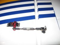
Also, if your aircraft has adjustable rocket-city style horns, then you should adjust the horn length for each servo so that they are approximately the same, and each servo moves approximately the same amount for the same control surface movement. This still will not be accurate enough to completely eliminate fighting, but it will make less programming work for you later.
Electronic Set-Up
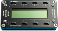
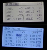
Now that you have good mechanical set-up on your surfaces, you can proceed to electronic set-up. For this procedure, pick one servo as a master. First I’ll explain how I would go about this by matching the servos with your transmitter. I am going to assume that you are using a transmitter that only has endpoint/EPA adjustment like the Aurora…I think JR has a “balance function†in the 11X and higher that works a little bit differently. Pick one servo as the “master.†I usually use the servo closest to the root as the master. Unscrew the ball links from the servo arms on all other servos that are on that surface. Use your sub-trim to center the surface, and then use EPA/ATV/Travel Adjust to set the throws in both directions. Set the amount of throw to the maximum amount of throw that you could want from that servo…usually I go with 40-45 degrees on the ailerons of a freestyle plane, and 20-30 on a sequence plane. Now, go to your slave servo. Adjust the sub-trim for that servo until the hole in the ball link lines up with the hole in the servo arm (ie, you can screw the ball link into the servo arm with no binding or fighting). Now move the control stick over to one extreme and hold it there. Put slight pressure on the control surface in the direction it is deflected until the servo stops whining/buzzing (this takes the load off of the surface and will allow you to more accurately matching the servos). You can also use a current meter to make sure that there is no load on the servo. Adjust the EPA for your slave servo until the hole for the ball link lines up with the arm (like you did in the center). Repeat this for the other direction. Now screw the ball link to the arm. Check to make sure that the servos are not fighting at center and at the extremes, either by listening for buzzing/whining from the servos or checking current consumption. You may have to fine tune the EPA and/or sub-trims by one or two percent to make sure it is just right. Note that some whining/buzzing/current draw is normal when the surface is fully deflected due to the slight load that the surface puts on the servos. You should be able to make the whining/buzzing/current draw stop when you push on the surface in the direction it is deflected. If you can do that, then your matching is done. You can probably see why I like this matching method best…it is simple, quick, straightforward, and provides plenty of power to the servos. If you ever need to change a servo at an event, you can do it quickly.
Programming Hitec digital servos
Programming Hitec servos is great because it is simple, light, and inexpensive. For example, a friend of mine flies a 100cc airplane on a DX-7 because we matched the servos properly. The elevators are on a single channel, which makes programming the radio very simple. However, it can be pretty time consuming.
I am going to assume you are using the HPP-21 or 21+ servo programmer. The hand-held version works the same way, but the HPP-21 and 21+ make it easier because it’s a little bit faster and easier to navigate.
If you look at the HPP-21 or 21+, there are 4 ports on it: three servo ports and a USB port. Plug it into your computer via a mini-USB cable in the USB port and plug a battery into it the Batt port. The other two ports, P1 and P2, do the same thing. Plugging servos into the P1 or P2 port allows you to test/program them. Install the HPP-21 software if you haven’t already, and start it up. You should also start up a spreadsheet program like Excel in another window. Take the ball links off of the servo arms on all servos.
Before I go any further, let me explain the different kinds of values you will be working with when you are doing this. The signal that comes out of your receiver is a pulse, delivered at 50 times per second, of varying length. The length of the pulse determines the position of the servo. A pulse that is 900 microseconds long tells the servo to be deflected all the way in one direction, and a pulse that is 2100 microseconds long tells it to be all the way deflected in the other direction. 1500 microseconds is center. When you program your servo, you tell the servo what position to reach at different pulse widths. When the programmer is in test mode, it is sending this pulse just like your receiver. I’ll refer to this as the receiver signal.
The next values you are concerned with are the center and endpoint values in the Hitec servo itself. These are the numbers you change when you program the servo. They range from about -230 to positive 230. These numbers don’t have any relation to anything in the real world like percentage, degrees, or microsecond pulse width. To make it easier to understand what they mean, you could think of them as percentage of servo movement, with -230 being -100 percent and 230 being 100 percent. If you are still confused you may get a better grasp of what they are as we program the servos.
The next value you are concerned with is deadband. Deadband can be thought of as a measurement of electronic slop in the servo…the way that a servo works is to constantly check the position of the output shaft and the commanded position, compare them, then power the motor to move the output shaft to the commanded position if it is not already there. Increasing deadband increases the amount of movement that the servo will allow of the output shaft before it powers the motor to drive it back to command position. The lowest/tightest value for deadband is 1, and it can go as high as 16 I think. I think that the units for deadband are the same as for endpoints and center. If you have servo fighting that you just can’t eliminate, you can change the deadband of one servo to 2 or 3 so that it will not fight. This may lead to reduced resolution at the surface, however. If you are using the Hitec programmer to set up servos where you are otherwise able to set the endpoints and center points (ie in the transmitter itself), then the only thing to bother programing is the deadband (set it to 1).
To start the servo programming, we will first need a master servo (just like for using the transmitter to match the servos). Again I usually pick the root servo. You will do minimal programming to this servo. Because the servo comes programmed out of the box to achieve full movement, you will probably not be able to match the slave servo to the master servo at the extremes of its movement…so we will need to first reduce its movement very slightly.
First, plug the programmer into just the root servo, and reset all values in the servo to defaults. Set the deadband to 1. Next use the option to reset the endpoints to default. Then, set the center position to 0, left position to -210, and right position to 210. Note that the servo will sweep through its movement as it does this, which is why you need to have the linkages disconnected as you program the servos. After you have done this, you can reconnect the linkage and ensure that the servo is working the aileron normally with the programmer in test mode.

Now comes the tedious part, programming the slave servo. Program the slave servo to the same values you programmed for the master servo earlier (-210, 0, 210). Remember to reset the servo every time you program it, reprogram all values every time you program it, and reprogram all values in the same order (program left, then center, then right, not right-center-left or right-left-center).
Now plug the master servo into the S1 port and the slave servo into the S2 port and put the programmer in test mode. Go to electronic center on the programmer, that’s 1500 microseconds. This may not keep the aileron at center but don’t worry about that. Hold the ball link for the slave servo over the threaded hole in the arm and observe its position and see if the servo center needs to be moved to the left or to the right. Now set the programmer almost to one extreme (say, 1050 microseconds) and check the ball link again…see if the servo needs to move more, or move less to match the root servo. Check it again almost at the other extreme (1950 microseconds) and see where it is.
For example, let’s imagine that the slave servo has to slightly rotate to the right to match the master servo at center, rotate slightly farther to the left to match when the master servo is rotated to the left, and slightly less to the right to match when the master servo is rotated to the right.
Now disconnect the master servo from the programmer and go back into program mode. Reset the servo endpoints to default, then program the following values into the slave servo for left, center, and right: -215, 5, 205. By doing this you have increased the movement to the left, slightly rotated the center position to the right, and decreased movement to the right. Again, the servo will sweep through its movement as you program it, so it must remain disconnected from the aileron.
Now plug both servos into the programmer again and go into test mode again, and check the center, left, and right again and see how close it is. Repeat the programming process for the slave servo again. It is useful of course to record the values you are programming either by hand or in your spreadsheet. It usually takes anywhere from 5-7 programming iterations to get it dead nuts perfect. Remember that you need to program all values every time you program the servo, so even if the center and left values are good and you need to only program the right value you still need to reprogram the center and left values to the same values as your previous iteration.
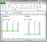
Once you get everything synced and matched, plug both servos into the receiver via your power expander or a very stout Y-harness, preferably with two power inputs. You now have two servos acting as one. Set your sub-trim to center the aileron and modify your endpoints to achieve the correct throw in either direction, and you’re done.
One of the most daunting (and important) tasks in setting up a giant scale airplane is setting up ganged servos (multiple servos on one surface). The challenge is in synchronizing the movements of the servos so that they do not fight each other, leading to undue stresses, servo wear, and battery use. Depending on your choice of servos, transmitter/receiver, and power distribution system (Power Expander, PowerBox, etc), you will have several options.

Options
The first option, and my favorite, is to use your transmitter to match your servos. If you have, for example, a 9 channel radio and a 100cc airplane with two servos per aileron, one per elevator, and one on the rudder, then you have enough channels to simply plug every servo into a unique port, and use the programming in the radio to match the servos. It should be noted that the 9303 and 9503, even though they have enough channels, lack the programming capability to do this.

The second option is to use a power distribution system that has built-in servo matching, such as the Smart-Fly PowerExpander EQ10. When you install your receiver in a system such as this, each channel from your receiver controls more than one port on the power expander. You can then program custom endpoints and center points on the power expander itself for each individual port. There are other power expander systems like the PowerExpander Pro that give the same signal on multiple ports and do not allow you to program the output of each individual port.
The third option is to use a matching device like a JR Matchbox or Smart-Fly Equalizer. These devices are similar to a Y-harness in that they take one input and split it into two or more outputs. However, each output can be programmed individually. They also usually have provisions for providing separate power to the servos plugged into them, so you don’t have to worry about pulling two or three servos worth of current through one plug. I haven’t used one of these devices yet so I won’t explain how to use it, but the mechanical set-up section still applies here.
The fourth option is the lightest, simplest, and cheapest, but the most cumbersome to set up: programming each servo directly. Some digital servos, such as Hitec, can be individually programmed to have custom center and endpoints. You can send each servo the same position signal and each servo will go to a custom programmed position. If you are using a power expander without built-in servo matching or a matching device like an equalizer or matchbox and you have more servos than channels, this is probably the only way to go.
Mechanical Set-Up
First, let’s look at mechanical set-up. Doing this properly will make much less work for you later during the electronic set-up, and in some cases, electronic matching will not be able to overcome poor mechanical set-up.
Good mechanical set-up mainly means two things. First, you are getting the proper amount of throw for a given amount of servo travel. If your servo arms are longer than they should be (or your control surface horns are too short), you will probably run your surfaces into the bevels before you reach 100% movement on the servo. This means you are putting undue stress on the servos and losing out on power and resolution. Conversely, if your arms are too short or your surface horns are too long, you will not get enough throw no matter what. This applies to all aircraft, even those without ganged servos.
Secondly, good mechanical set-up means that the surfaces are achieving equal throw in both directions with equal servo movement. If the pivot point on your control surface horns is directly over the hinge line, this will be achieved by having the servo arm parallel to the hinge line. If you have horns that place the pivot point further back (over the surface, rather than the hinge line), then that’s OK too. This is usually the case with older rocket-city style adjustable horns, and we can accommodate for them. To achieve this second goal, you should first assemble the linkage on the control surface. If the pivot points for your horns are over the hinge line, then adjust the pushrod length by turning the turnbuckle until the servo arm is parallel with the hinge line…you’re done.

If it’s not, then you can measure the movement of the servo arm with a protractor as you also measure the movement of the surface. Adjust the length of the pushrod until the movement of the servo is equal on either side of neutral for equal control surface movement on either side of neutral. IE, if the servo must move 50 degrees in one direction for the surface to achieve 40 degrees of movement up, the servo should also need to move 50 degrees in the opposite direction to achieve 40 degrees of control surface movement down. Am I making any sense? You can also test this by using a servo tester or your transmitter instead of a protractor on your servo. 100% ATV in one direction should get you the same throw as 100% ATV in the other direction. Also, while it’s important that these be matched, it’s not important that they be matched with extremely high precision…so don’t pull your hair out if you can’t get them matched to within 1 degree. This applies to all airplanes as well.

Also, if your aircraft has adjustable rocket-city style horns, then you should adjust the horn length for each servo so that they are approximately the same, and each servo moves approximately the same amount for the same control surface movement. This still will not be accurate enough to completely eliminate fighting, but it will make less programming work for you later.
Electronic Set-Up
Now that you have good mechanical set-up on your surfaces, you can proceed to electronic set-up. For this procedure, pick one servo as a master. First I’ll explain how I would go about this by matching the servos with your transmitter. I am going to assume that you are using a transmitter that only has endpoint/EPA adjustment like the Aurora…I think JR has a “balance function†in the 11X and higher that works a little bit differently. Pick one servo as the “master.†I usually use the servo closest to the root as the master. Unscrew the ball links from the servo arms on all other servos that are on that surface. Use your sub-trim to center the surface, and then use EPA/ATV/Travel Adjust to set the throws in both directions. Set the amount of throw to the maximum amount of throw that you could want from that servo…usually I go with 40-45 degrees on the ailerons of a freestyle plane, and 20-30 on a sequence plane. Now, go to your slave servo. Adjust the sub-trim for that servo until the hole in the ball link lines up with the hole in the servo arm (ie, you can screw the ball link into the servo arm with no binding or fighting). Now move the control stick over to one extreme and hold it there. Put slight pressure on the control surface in the direction it is deflected until the servo stops whining/buzzing (this takes the load off of the surface and will allow you to more accurately matching the servos). You can also use a current meter to make sure that there is no load on the servo. Adjust the EPA for your slave servo until the hole for the ball link lines up with the arm (like you did in the center). Repeat this for the other direction. Now screw the ball link to the arm. Check to make sure that the servos are not fighting at center and at the extremes, either by listening for buzzing/whining from the servos or checking current consumption. You may have to fine tune the EPA and/or sub-trims by one or two percent to make sure it is just right. Note that some whining/buzzing/current draw is normal when the surface is fully deflected due to the slight load that the surface puts on the servos. You should be able to make the whining/buzzing/current draw stop when you push on the surface in the direction it is deflected. If you can do that, then your matching is done. You can probably see why I like this matching method best…it is simple, quick, straightforward, and provides plenty of power to the servos. If you ever need to change a servo at an event, you can do it quickly.
Programming Hitec digital servos
Programming Hitec servos is great because it is simple, light, and inexpensive. For example, a friend of mine flies a 100cc airplane on a DX-7 because we matched the servos properly. The elevators are on a single channel, which makes programming the radio very simple. However, it can be pretty time consuming.
I am going to assume you are using the HPP-21 or 21+ servo programmer. The hand-held version works the same way, but the HPP-21 and 21+ make it easier because it’s a little bit faster and easier to navigate.
If you look at the HPP-21 or 21+, there are 4 ports on it: three servo ports and a USB port. Plug it into your computer via a mini-USB cable in the USB port and plug a battery into it the Batt port. The other two ports, P1 and P2, do the same thing. Plugging servos into the P1 or P2 port allows you to test/program them. Install the HPP-21 software if you haven’t already, and start it up. You should also start up a spreadsheet program like Excel in another window. Take the ball links off of the servo arms on all servos.
Before I go any further, let me explain the different kinds of values you will be working with when you are doing this. The signal that comes out of your receiver is a pulse, delivered at 50 times per second, of varying length. The length of the pulse determines the position of the servo. A pulse that is 900 microseconds long tells the servo to be deflected all the way in one direction, and a pulse that is 2100 microseconds long tells it to be all the way deflected in the other direction. 1500 microseconds is center. When you program your servo, you tell the servo what position to reach at different pulse widths. When the programmer is in test mode, it is sending this pulse just like your receiver. I’ll refer to this as the receiver signal.
The next values you are concerned with are the center and endpoint values in the Hitec servo itself. These are the numbers you change when you program the servo. They range from about -230 to positive 230. These numbers don’t have any relation to anything in the real world like percentage, degrees, or microsecond pulse width. To make it easier to understand what they mean, you could think of them as percentage of servo movement, with -230 being -100 percent and 230 being 100 percent. If you are still confused you may get a better grasp of what they are as we program the servos.
The next value you are concerned with is deadband. Deadband can be thought of as a measurement of electronic slop in the servo…the way that a servo works is to constantly check the position of the output shaft and the commanded position, compare them, then power the motor to move the output shaft to the commanded position if it is not already there. Increasing deadband increases the amount of movement that the servo will allow of the output shaft before it powers the motor to drive it back to command position. The lowest/tightest value for deadband is 1, and it can go as high as 16 I think. I think that the units for deadband are the same as for endpoints and center. If you have servo fighting that you just can’t eliminate, you can change the deadband of one servo to 2 or 3 so that it will not fight. This may lead to reduced resolution at the surface, however. If you are using the Hitec programmer to set up servos where you are otherwise able to set the endpoints and center points (ie in the transmitter itself), then the only thing to bother programing is the deadband (set it to 1).
To start the servo programming, we will first need a master servo (just like for using the transmitter to match the servos). Again I usually pick the root servo. You will do minimal programming to this servo. Because the servo comes programmed out of the box to achieve full movement, you will probably not be able to match the slave servo to the master servo at the extremes of its movement…so we will need to first reduce its movement very slightly.
First, plug the programmer into just the root servo, and reset all values in the servo to defaults. Set the deadband to 1. Next use the option to reset the endpoints to default. Then, set the center position to 0, left position to -210, and right position to 210. Note that the servo will sweep through its movement as it does this, which is why you need to have the linkages disconnected as you program the servos. After you have done this, you can reconnect the linkage and ensure that the servo is working the aileron normally with the programmer in test mode.

Now comes the tedious part, programming the slave servo. Program the slave servo to the same values you programmed for the master servo earlier (-210, 0, 210). Remember to reset the servo every time you program it, reprogram all values every time you program it, and reprogram all values in the same order (program left, then center, then right, not right-center-left or right-left-center).
Now plug the master servo into the S1 port and the slave servo into the S2 port and put the programmer in test mode. Go to electronic center on the programmer, that’s 1500 microseconds. This may not keep the aileron at center but don’t worry about that. Hold the ball link for the slave servo over the threaded hole in the arm and observe its position and see if the servo center needs to be moved to the left or to the right. Now set the programmer almost to one extreme (say, 1050 microseconds) and check the ball link again…see if the servo needs to move more, or move less to match the root servo. Check it again almost at the other extreme (1950 microseconds) and see where it is.
For example, let’s imagine that the slave servo has to slightly rotate to the right to match the master servo at center, rotate slightly farther to the left to match when the master servo is rotated to the left, and slightly less to the right to match when the master servo is rotated to the right.
Now disconnect the master servo from the programmer and go back into program mode. Reset the servo endpoints to default, then program the following values into the slave servo for left, center, and right: -215, 5, 205. By doing this you have increased the movement to the left, slightly rotated the center position to the right, and decreased movement to the right. Again, the servo will sweep through its movement as you program it, so it must remain disconnected from the aileron.
Now plug both servos into the programmer again and go into test mode again, and check the center, left, and right again and see how close it is. Repeat the programming process for the slave servo again. It is useful of course to record the values you are programming either by hand or in your spreadsheet. It usually takes anywhere from 5-7 programming iterations to get it dead nuts perfect. Remember that you need to program all values every time you program the servo, so even if the center and left values are good and you need to only program the right value you still need to reprogram the center and left values to the same values as your previous iteration.

Once you get everything synced and matched, plug both servos into the receiver via your power expander or a very stout Y-harness, preferably with two power inputs. You now have two servos acting as one. Set your sub-trim to center the aileron and modify your endpoints to achieve the correct throw in either direction, and you’re done.
Last edited by a moderator:

