• If you are new to GiantScaleNews.com, please register, introduce yourself, and make yourself at home.

    We're 1st in Giant Scale RC because we've got the best membership on the internet! Take a look around and don't forget to register to get all of the benefits of GSN membership!

    Welcome!
  • Unless you are a paid advertiser NO more posting advertisement in the individual vendor forums. You may post in the Manufacturer's Announcements section only but only ONCE a month unless your a paid advertiser.

AJ Laser 230z 73" Build Thread

AKNick

640cc Uber Pimp
AJ 73" Laser 230z

Control Horn Installation.

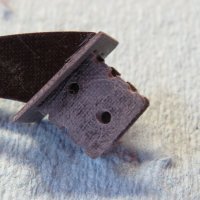
As you can tell, I scuffed up the lower section pretty good of the control horn along with the underbelly of the plate with some sand paper just like the elevator joiner.. I even made a few notches with my dremel just cuz, heck it probably lowered its structural integrity for all I know ha!

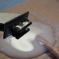
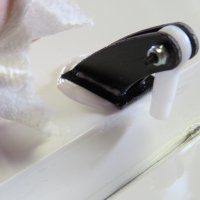
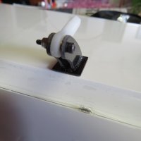
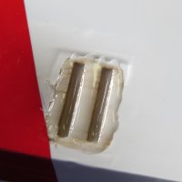
I mixed up some 30min epoxy with some microbaloons to give it an almost pasty consistency. I think it helps keep the epoxy all in one place, and is supposed to lighten it up... but in retrospect your probably not saving THAT much weight. Anyways, dab it on all the contacting surfaces and the control horn slots, slap them together and wipe off the excess epoxy, then wipe clean with alcohol. Make sure the control surface has full travel before the epoxy sets up, one way to do it is to tape the control surface in the full deflection position and let it set up. Note that that ball link is temporarily installed to maintain the proper control horn separation.
IMG_1662.JPGIMG_1664.JPGIMG_1663.JPGIMG_1665.JPGIMG_1666.JPG

I don't think a tornado could even pull these horns out ;)
 

AKNick

640cc Uber Pimp
AJ 73" Laser 230z

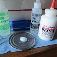
Microballooning it up:

IMG_1771.JPGIMG_1772.JPG

A shot sized cup would be a better method for this FYI. It'll keep the glass balloons from going all over the place.
 

AKNick

640cc Uber Pimp
AJ 73" Laser 230z

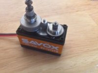
I got my SAVOX SV-1270TG Servos from Code3 Innovations. You can PM him on FG or visit his website.

Dimensions(mm): 40.3x20.2x37.2
Weight(g): 56
Speed(@6.0V sec/60): .14
Torque(@6.0V oz-in): 361.1
Speed(@7.4V sec/60): .11
Torque(@7.4V oz-in): 487.1
Gear: Titanium & Aluminum
Bearing: 2BB
Case: Aluminum

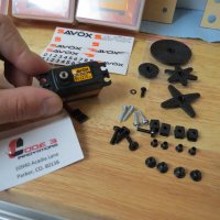
Here is a pic of the goods included.
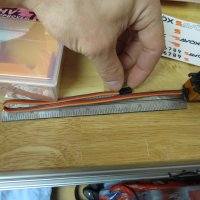
I measured the wire length for anybody that is curious (11.25" w/o the connector).
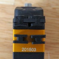
Apparently there is a right way to put the rubber grommets on your servos along with the metal bushing... I guess the bushing is actually supposed to be inserted from the bottom? I've been doing it wrong all these years I guess, so yes this picture is wrong... It wont make the plane fall out of the sky though

IMG_1673.JPGIMG_1671.JPGIMG_1678.JPG

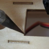
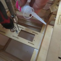
These servos you'll find that you will have to bevel both sides with your xacto blade. I did it with the butt of the knife facing aft on both sides. Then you can see my clever picture of showing the three step process of (not marking sorry! I find the largest drill bit that fits inside the servo grommet and lightly twist with my finger - this gives you the exact center) drilling, tapping, and curing the threads with Thin CA.

IMG_1674.JPGIMG_1769.JPG
 
Last edited by a moderator:

AKNick

640cc Uber Pimp
AJ 73" Laser 230z

Okay, so this is where I don't want to scare or shy away anybody from either products. So read before you judge any picture by itself. Just sharing my research - take it or leave it.

Servo Tray Failure by another a laser 73" owner who essentially had lightly crashed/hard landing where the plane hit rudder first. That obviously puts a stress on the frame that you wouldn't get in flight... unless you are a hardcore tail-toucher or sumpthin.

servo tray break.jpg

Next pic is from an aircraft that once again had a previous "hard/abnormal landing" and the splines had stripped on his ailerons? He wasn't able to catch this on his pre-flight because the splines had caught and moved away from the stripped section. With that said, all servos are not perfect, and accidents do happen. This is a very popular servo, and eventually stuff breaks - and the world keeps spinning if you catch my drift. I still trust them enough obviously.

1270 failure.jpg

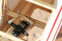
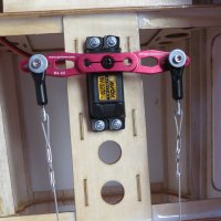
Here is my Rudder Servo installed. 4-40 SeCraft ball links on Spot-On RC V1 3.5" (using the 3" holes) futaba splines, stock cable, 15-45lb crimps, and a turnbuckle pushrod cut in half drilled, sanded, and screwed into place. Either that or order something similar. Guess I found the MacGyver in me.

Note that I epoxied the servo tray along with a extra fillet mixed with my micro-balloons. ;)

IMG_1831.JPG
 

AKNick

640cc Uber Pimp
AJ 73" Laser 230z

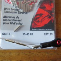
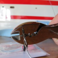
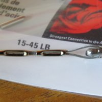
I personally don't really like the crimp quality of the included crimps, so I went with the 15-45lb Berkley fishing line crimps. I used two for insurance, they feel 1000 times better IMHO than their counterparts. If you were to buy new line, I'm guessing it's 45lb or so? I just used the line the model came with. You see a lot people adding CA into crimps for the added security, I don't really feel inclined to do so with these crimps. Who knows, maybe I will anyways!

IMG_1826.JPGIMG_1827.JPGIMG_1828.JPG

Who puts a Qty of 33??? weird... seems like a random number:confused:
 

AKNick

640cc Uber Pimp
AJ 73" Laser 230z

Rudder Attachment:

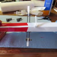
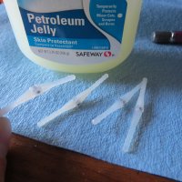
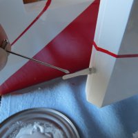
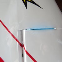
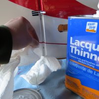
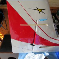
Attached the control horns as I previously mentioned. I used a pin to dub on some petroleum jelly so the epoxy wouldn't get into the hinge itself, most regular people use Vaseline... I just didn't have some on hand so I improvised. Then I proceeded to dub on the epoxy on the hinge pin and basically filled the hole it goes into as best I can. The idea is that you smear the epoxy to make contact with all the internal wood and hinge pin. Move the rudder around to make sure the pins are tracking strait and that you get full deflection. Note that I put a piece of folded paper in-between the rudder and the top of the vertical to make sure it doesn't set up resting on top of the rudder... This is more of an issue with pinned-flat hinges or working with old CA... I used lacquer thinner to remove the excess epoxy from the hinge area. Tape it all in place and let it fully cure up. I always leave my mixed up epoxy near my project to use as a reference for how set up it is before I remove the tape and start wagging the tail, presuming a knife edge position, and making airplane noises.... okay maybe just in my head at this time.

IMG_1661.JPGIMG_1770.JPGIMG_1773.JPGIMG_1775.JPGIMG_1774.JPGIMG_1777.JPG
 

AKNick

640cc Uber Pimp
AJ 73" Laser 230z

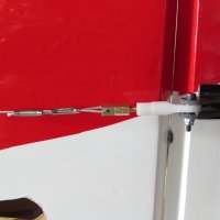
After the rudder is cured, Fire up the RX and make sure your rudder arm is moving in the right direction and that it's as centered as you can get it, now you can attach the control cables up, center the rudder, tighten the cables (I found that the crimps I used slid with a little tension, enough to essentially pull both cables together taught), then Crimp, and re tighten the cables as necessary. Note that I did criss-cross the cables inside the fuse.

IMG_1829.JPG

Ackermann.... With this setup (Strait servo arm @3" spacing, with criss-crossing the cables, and with the Mfgrs control horns). It seems that the cables are always taught. I was very pleased to not have to buy an offset arm. Only at the maximum deflection where I can just start to feel the non-pulling cable get a tiny bit slack.

For those of you who don't know about Ackermann. It was geometry discovered in the 1800's, Mr Rudolf Ackermann essentially patented this Geometry.

From Wikipedia:
"Ackermann steering geometry is a geometric arrangement of linkages in the steering of a car or other vehicle designed to solve the problem of wheels on the inside and outside of a turn needing to trace out circles of different radius."

This concept is essentially the same with our Pull-Pull Rudders. What effects it is the attaching distance, and where they are located in reference to the pivot point. We at least want to have some Ackermann built in so that the cables are taught when centered, this minimizes control surface flutter, and when the servo arm moves the pulling side remains taught but the opposite line gets a little slack. This is OK since when the aircraft is flying, the amount of air flowing across the control surface cannot let it blow back the other way.
In a perfect world I would like to see the cables taught all the time... in this case... they are!!!! :grrreat:
 
Ah, good to know! I was always a bit curious as to why we use the offset. I always just used them anyway, so just to clarify, can I use one on this plane or is a straight arm better? Still need to order arms.
 

AKNick

640cc Uber Pimp
Ah, good to know! I was always a bit curious as to why we use the offset. I always just used them anyway, so just to clarify, can I use one on this plane or is a straight arm better? Still need to order arms.

I personally think this setup is great with just a plain old strait arm at 3" spacing. I think the offset look the best, but not needed for this application. I think people call this "Neutral Ackermann". What you don't want is for the cables to be loose in the neutral position, and get tight as it moves. My 71" slick has it the other way with a strait arm, I think the offset arm would essentially solve my geometry issue there.
 
Top