• If you are new to GiantScaleNews.com, please register, introduce yourself, and make yourself at home.

    We're 1st in Giant Scale RC because we've got the best membership on the internet! Take a look around and don't forget to register to get all of the benefits of GSN membership!

    Welcome!
  • Unless you are a paid advertiser NO more posting advertisement in the individual vendor forums. You may post in the Manufacturer's Announcements section only but only ONCE a month unless your a paid advertiser.

WrongWayRc 50-60cc GBR (GeeBeeRacer) Build thead

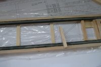
BTW, the first photo in post number 9 there is a 3/8 x 1/2 inch hardwood rail that continues the 3/8 x 1/2 balsa box outline into the center section and that is epoxied to the wing center section and continues to the nose piece.


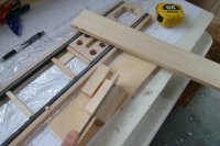
As a general rule on these planes... anything forward of the wing tube we try as much as possible to use epoxy or gorilla glue on the fuse and the reason is the pulse from the gasoline engine can and will loosen CA glue that is used in forward locations. In the picture I have epoxied the hardwood rail to the ply center section and it will go forward to attach the lite ply nose piece for strength there.

When done the two hardwood rails will box out the engine cut out areas with strength for the nose pieces which are getting all of the vibration. Anything forward of the firewall is not structural but still needs to be able to take the vibration.
 
Last edited by a moderator:
Richard-

Great points RE: epoxy, GG, and vibration from the engine. It's worth noting, that all CA can be successfully used if building a big electric, but honestly, at 17# flat, and a 6 month+ build, I didn't save either weight nor time going all CA on my WWRC 50cc LamSuk!

-Case
 
So both fiberglass tubes are set. BTW, I scuffed them up before setting them in gorilla glue for best bond. Once in place I lock them in with thick CA zip kicked to keep any of the expanding glue from moving them. Just a spot here and a spot there.

Next is the horizontal stab saddle which is CNC router ed. There are two of them and both fit perfectly between the tubes. (if not I can lightly sand) I use thick CA for each one and just line up the holes on the lite ply area below.

Just forward of the saddle is the hardwood rails for servo hole. I start with one piece of 3/8 x 1/4 stick from the kit material and thick CA it down, then 3/8 x 1/4 basswood on top. I already know which side of the fuse (left) that I will screw in my servo..... I keep my servo linkage/arms on the opposite side of the engine exhaust. Before gluing in the second rail check fit with the servo you will use.
 
Last edited by a moderator:
I then cut from a 3/8x 1/2 balsa stick the uprights that fit in between the tubes and glued them in with thick CA.
 

Attachments

  • P1010446(1).JPG
    P1010446(1).JPG
    141.6 KB · Views: 223
  • P1010447(1).JPG
    P1010447(1).JPG
    189.5 KB · Views: 255
Last edited by a moderator:
There are 1/2 thick by one inch wide...and one 1/2 by 2 1/4 inch block (per the plans) that are place over the anti rotation pins and the wing tube cut out. I cut them from the 1/2 inch stock that comes with the kit to fit in between the tubes/rails. These are glued down with thick CA.

After dry I flip over the center section and run a 1/4 inch drill bit through the 4 holes that are the anti rotation and wing bolt holes. These holes need to be perfectly perpendicular and if not, just open them up a little... If angled they will affect gluing the second half of the ply center section later. If the balsa in between the ply holes is a little big, it will be filled with the gorilla glue later in the build when we glue in the anti rotation pins..
 

Attachments

  • P1010450(1).JPG
    P1010450(1).JPG
    134.5 KB · Views: 234
Last edited by a moderator:
I have cut the 3/8 by half hardwood piece that goes between the rails and acts as the attach point for the firewall later. In this picture I have sanded it to fit in the slot and behind it is the 1/2 inch landing gear ply block that comes in the kit.

I have marked out a spot for my throttle servo that will fit between the landing gear block and also will be out of the way of the wing when it is attached. This orientation will give me a straight shot to the carb arm with a carbon rod extending through the firewall later in the build. I checked that my servo will fit and it does.
 

Attachments

  • P1010450(1).JPG
    P1010450(1).JPG
    134.5 KB · Views: 234
Last edited by a moderator:
Here is a mock up of the 3/4 inch hardwood triangle stock that will back up the engine firewall, behind it is the landing gear and in back of that the servo for throttle.

You can see in the ply piece above where I have traced out the wing rib root and laid out the servo location. Actually, I moved the servo about a half inch back of that so it would clear the landing gear hard wood block.
 

Attachments

  • P1010448(1).JPG
    P1010448(1).JPG
    151 KB · Views: 251
Last edited by a moderator:
Top