• If you are new to GiantScaleNews.com, please register, introduce yourself, and make yourself at home.

    We're 1st in Giant Scale RC because we've got the best membership on the internet! Take a look around and don't forget to register to get all of the benefits of GSN membership!

    Welcome!

Addiction XL Build??

I know this isn't Giant Scale, or Gas Powered, but is anyone interested in a build thread? And can I post it here, or is there a better place? I'm taking a break from the Cub and have started assembly of this one for Spring time flying. Blessed day to all!
 

Attachments

  • addictionXL.jpg
    addictionXL.jpg
    165.4 KB · Views: 1,106

Snoopy1

640cc Uber Pimp
Love to see you build it I have had one for a number of years now one of my favourite planes. You will be amazed at the quality and its ability. Did you get the new 60 size motor. I have the older generation one.
 
Love to see you build it I have had one for a number of years now one of my favourite planes. You will be amazed at the quality and its ability. Did you get the new 60 size motor. I have the older generation one.

Yep, got the new 60 motor and new 80amp ESC. I've been flying the Addiction X for years now. The wife got me the XL for Christmas this year. I've been wanting one for some time now. I've also been flying the Katana MX for a couple of years. Love the PA aircraft!
 
With all the PA aircraft, they recommend no gap between the control surface and flying surface, and want 50* of travel. But it's not possible without re-shaping the leading edge of the ailerons and elevator. I choose not too, and just get what I can on throws. It's usually about 35 to 40* max. The first step is to get the ailerons hinged to the wings. I substituted Radio South hinges for the stock ones. I rounded the hinges, marked center, and pinned them for installation. I also removed the covering from the hinge slots and ironed them down. Had to open them up a little more for the new hinges. Got the ailerons mounted on both wings.
 

Attachments

  • IMG_3314 (2).JPG
    IMG_3314 (2).JPG
    415.3 KB · Views: 366
  • IMG_3317.JPG
    IMG_3317.JPG
    488.1 KB · Views: 368
  • IMG_3318 (2).JPG
    IMG_3318 (2).JPG
    339.8 KB · Views: 351
Last edited:
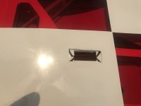
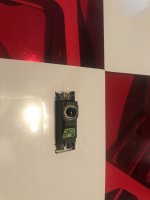
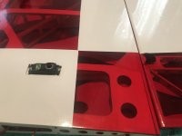
Next step is to work on the aileron servo installation. I opened up the servo hole by cutting down the center, then a diagonal cut from the corners to the center and ironing it all down into the servo hole. Once the servo is in place. Use a small drill bit to pre-drill the holes for the servo screws. The servos did come with fully threaded screws, so I used them. Use the screws to kind of tap the hole, by turning it in 1/2 turn at a time, then backing it back out, and going another 1/2 turn in, until the hole is threaded. I put a drop of thin CA in each hole to harden the threads before installing the servos.
 

Attachments

  • IMG_3315.JPG
    IMG_3315.JPG
    343.3 KB · Views: 359
  • IMG_3319.JPG
    IMG_3319.JPG
    346.8 KB · Views: 361
Prepped the carbon horns and got them glued in. I used a round file to open up the clevis pin hole just a tad. Prepped the rods as per instructions, and got them glued in with epoxy. The carbon rods were just the right length in this one, no need to cut any off. I also had to drill the carbon servo arm extension holes just a bit larger for the servo arm screw, and used the round file to open up the ball link screw hole just a bit as well. The kit comes with extra covering for the hinge gap. I got that on as well. Wings are done!
 

Attachments

  • IMG_3320.JPG
    IMG_3320.JPG
    560.6 KB · Views: 358
  • IMG_3321.JPG
    IMG_3321.JPG
    382.4 KB · Views: 349
  • IMG_3323.JPG
    IMG_3323.JPG
    347.3 KB · Views: 356
  • IMG_3324 (2).JPG
    IMG_3324 (2).JPG
    327.3 KB · Views: 366
Ok, I decided to work on the motor mount next, as it takes several steps to complete. First step is to glue in 4 small pieces of fiberglass on the inside corners of the firewall. Use extra epoxy to reinforce the motor box joints throughout. Next, epoxy on the fiber reinforcements. Then epoxy on the remaining fiberglass strip to the bottom of the motor box and up around the sides.
 

Attachments

  • IMG_3325.JPG
    IMG_3325.JPG
    780.9 KB · Views: 354
  • IMG_3326.JPG
    IMG_3326.JPG
    393.3 KB · Views: 346
  • IMG_3327.JPG
    IMG_3327.JPG
    460.6 KB · Views: 332
  • IMG_3330 (2).JPG
    IMG_3330 (2).JPG
    293.8 KB · Views: 340
Top