Capt.Roll
70cc twin V2
Seems like there is always “little things†that you like to do so your ARF is the way you want it.
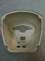
Some other owners of this ARF posted on FG about the cowl being pretty thin, especially around the prop/spinner opening. I would agree as it seems that the cowl could be accidentally damaged. Since my manual choke access is on the left front side I took some 18g (very light stuff) glass cloth and reinforced (circled area) the forward cowl openings, the forward quarter top and bottom of the cowl and around the ply mounting ring. I didn't get a before/after weight of the cowl but the reinforcement didn't add much.
The spark plug lead passes pretty close to the muffler so I didn't want excessive heat to start to degrade the plug wire. I took a short piece of high temperature hose and covered the plug wire to provide some heat shielding to the wire.
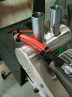
I’m hoping the upper and lower cowl openings are large enough to provide adequate air flow over the engine for cooling. There is not an exit vent in the cowl to allow the air out. With a full length canister tunnel I’m sure the vent is supposed to be cut somewhere toward the rear of the tunnel. Since I’m not going to run a can/pipe I cut the covering out directly behind the firewall for my exit vent. To keep the air from going back into the fuse/tunnel I made and installed an air director to help route the air down and out of this exit. It’s painted to match the firewall and secured in place with two screws and a piece of tri-stock. It’s easy to remove should I need access to the something behind it.
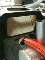
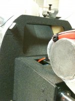
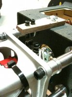
The high and low needles on the EME60 are facing up on my install; having access to the needles with the cowl on and engine running when tuning the engine will be nice. I mounted a DA style fuel filler on top of the cowl directly over the H/L needles. The screwdriver guide is made from ¼†ply and two short pieces of CF tube. Haven’t tested the setup with the engine running but the guide tubes allow the screwdriver to drop right on top of the needles.
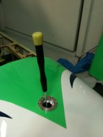
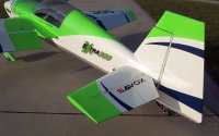
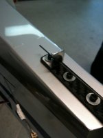
The rudder is removable on my Extra so there is a piece of piano wire that needs to be secured. I made a small bracket out of aluminum and fastened it to the CF tail wheel bracket using one of the existing mounting bolts. The aluminum bracket has a small slot cut in it that leads to a rubber grommet mounted in the middle of the bracket. The rudder hinge pin just pushes into the grommet; this also keeps any RF noise from being generated from metal to metal contact.
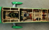
CG location is recommended at 6 – 7 inches from the leading edge at the wing root; this is basically right at/under the wing tube. The final layout of the on board components put me right around the 6 to 6.5 inch mark. Maiden flight and initial trim will be with this CG and then make any adjustments if needed.
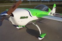
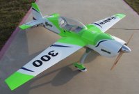
Nothing really left to do before the maiden flight other than look at it sitting on the floor.......ha. A nice calm, warm day should be right around the corner now that spring is just a few weeks away. Probably check my control surface movements and rates one more time before taking it out for the first flight.
Some other owners of this ARF posted on FG about the cowl being pretty thin, especially around the prop/spinner opening. I would agree as it seems that the cowl could be accidentally damaged. Since my manual choke access is on the left front side I took some 18g (very light stuff) glass cloth and reinforced (circled area) the forward cowl openings, the forward quarter top and bottom of the cowl and around the ply mounting ring. I didn't get a before/after weight of the cowl but the reinforcement didn't add much.

The spark plug lead passes pretty close to the muffler so I didn't want excessive heat to start to degrade the plug wire. I took a short piece of high temperature hose and covered the plug wire to provide some heat shielding to the wire.

I’m hoping the upper and lower cowl openings are large enough to provide adequate air flow over the engine for cooling. There is not an exit vent in the cowl to allow the air out. With a full length canister tunnel I’m sure the vent is supposed to be cut somewhere toward the rear of the tunnel. Since I’m not going to run a can/pipe I cut the covering out directly behind the firewall for my exit vent. To keep the air from going back into the fuse/tunnel I made and installed an air director to help route the air down and out of this exit. It’s painted to match the firewall and secured in place with two screws and a piece of tri-stock. It’s easy to remove should I need access to the something behind it.


The high and low needles on the EME60 are facing up on my install; having access to the needles with the cowl on and engine running when tuning the engine will be nice. I mounted a DA style fuel filler on top of the cowl directly over the H/L needles. The screwdriver guide is made from ¼†ply and two short pieces of CF tube. Haven’t tested the setup with the engine running but the guide tubes allow the screwdriver to drop right on top of the needles.


The rudder is removable on my Extra so there is a piece of piano wire that needs to be secured. I made a small bracket out of aluminum and fastened it to the CF tail wheel bracket using one of the existing mounting bolts. The aluminum bracket has a small slot cut in it that leads to a rubber grommet mounted in the middle of the bracket. The rudder hinge pin just pushes into the grommet; this also keeps any RF noise from being generated from metal to metal contact.

CG location is recommended at 6 – 7 inches from the leading edge at the wing root; this is basically right at/under the wing tube. The final layout of the on board components put me right around the 6 to 6.5 inch mark. Maiden flight and initial trim will be with this CG and then make any adjustments if needed.

Nothing really left to do before the maiden flight other than look at it sitting on the floor.......ha. A nice calm, warm day should be right around the corner now that spring is just a few weeks away. Probably check my control surface movements and rates one more time before taking it out for the first flight.

