BalsaDust
Moderator
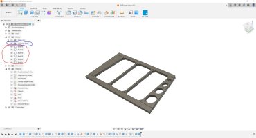
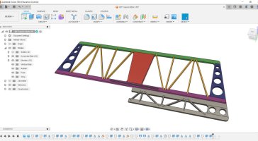
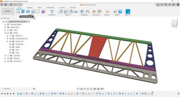
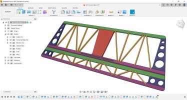
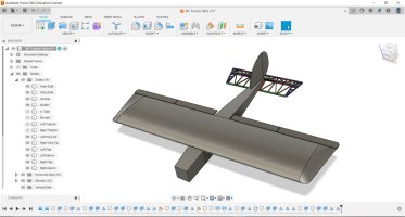
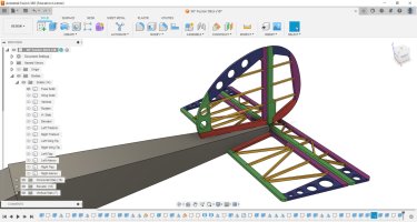
Lets get back to this project. First off as I had said before be sure you have created a second save point for your project now that the solid model is complete. So lets start with the tail bits as they are pretty simple.
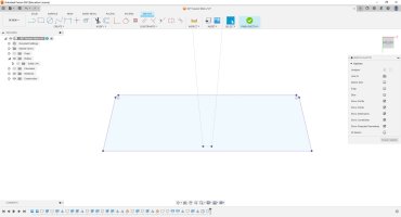
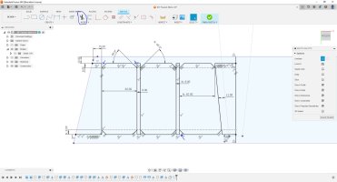
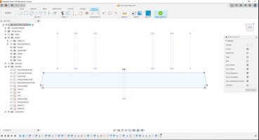
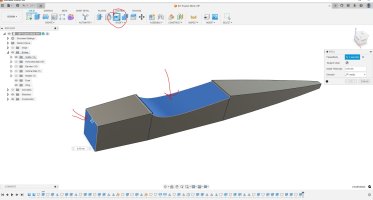
H1- I have just sketched on the bottom of the horizontal stab solid. I projected the fuse to my sketch as construction lines and the stab itself as normal lines. Then I turned those solids off so they where no longer in my way and I didn't alter them in any way.
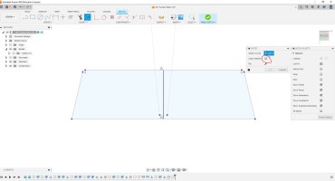
H2- Here I have drawn a single center line and now I want to offset some things. Note I have disabled the chain selection for this.
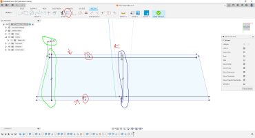
H3- Here you can see that I used that offset tool to offset the LE the TE and one fuse side I went with 12mm. Also I drew a single line at the tip and dimensioned it from a known point.
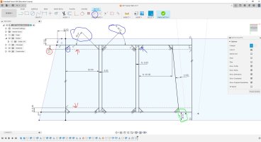
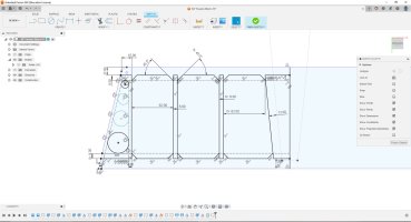
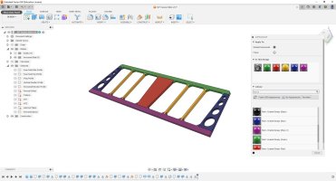
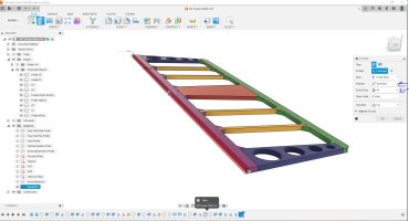
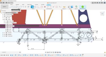
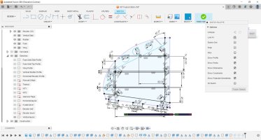
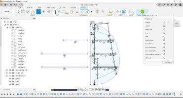
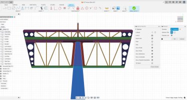
H4- Ok from here the sketch is going to start getting cluttered but for parts like this it is easier on the software to have this single more complex sketch. First note I changed my offset on the TE piece from 12mm to 15mm as we need to account for the bevel. you can see I have drawn in two additional sticks. Also marked in red I added a construction line that the front and rear. I use this as the point to draw in the bevels marked with blue. Note here I only dimensioned the angle on two of them and from there I used the parallel constraint to match up the rest of them.
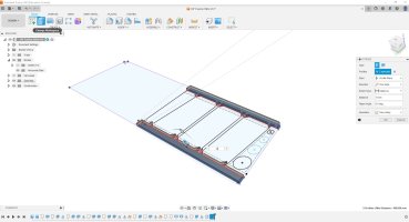
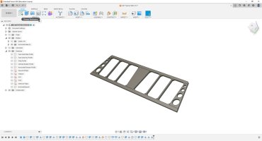
H5- Here I have used the trim tool to go in and cut away all the lines I don't want any more.
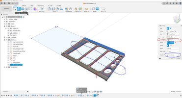
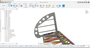
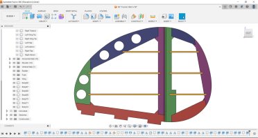
H6- Lastly to finish up the sketch lets add some lighten holes in the tip portion. This isn't needed but I like to save weight everywhere possible.

