• If you are new to GiantScaleNews.com, please register, introduce yourself, and make yourself at home.

    We're 1st in Giant Scale RC because we've got the best membership on the internet! Take a look around and don't forget to register to get all of the benefits of GSN membership!

    Welcome!

Airplane Design Fusion 360

BalsaDust

Moderator
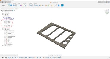
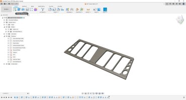
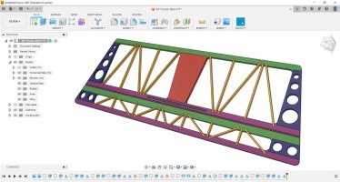
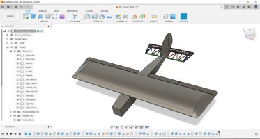
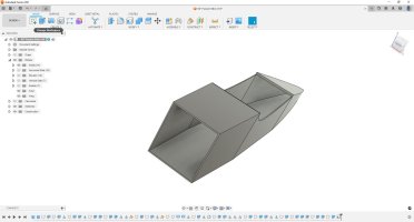
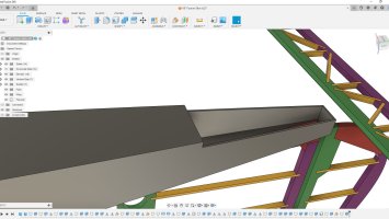
Lets get back to this project. First off as I had said before be sure you have created a second save point for your project now that the solid model is complete. So lets start with the tail bits as they are pretty simple.

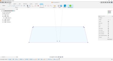
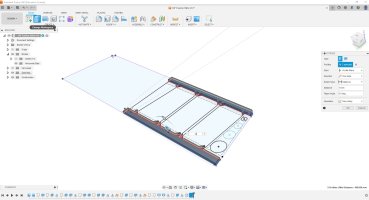
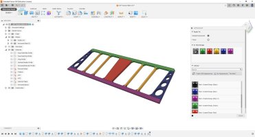
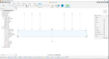
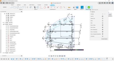
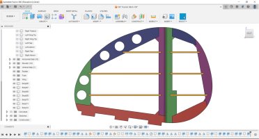
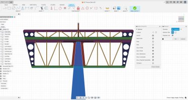
H1- I have just sketched on the bottom of the horizontal stab solid. I projected the fuse to my sketch as construction lines and the stab itself as normal lines. Then I turned those solids off so they where no longer in my way and I didn't alter them in any way.
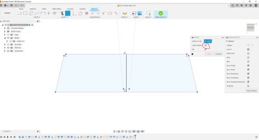
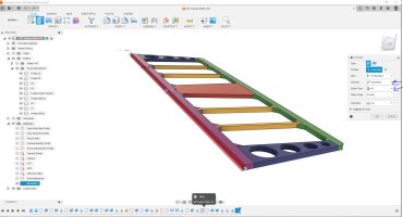
H2- Here I have drawn a single center line and now I want to offset some things. Note I have disabled the chain selection for this.
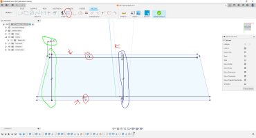
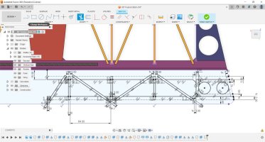
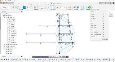
H3- Here you can see that I used that offset tool to offset the LE the TE and one fuse side I went with 12mm. Also I drew a single line at the tip and dimensioned it from a known point.
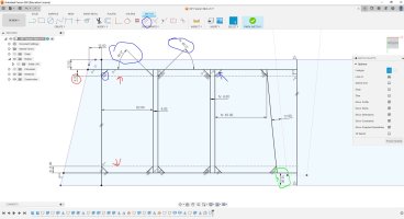
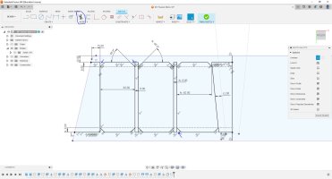
H4- Ok from here the sketch is going to start getting cluttered but for parts like this it is easier on the software to have this single more complex sketch. First note I changed my offset on the TE piece from 12mm to 15mm as we need to account for the bevel. you can see I have drawn in two additional sticks. Also marked in red I added a construction line that the front and rear. I use this as the point to draw in the bevels marked with blue. Note here I only dimensioned the angle on two of them and from there I used the parallel constraint to match up the rest of them.
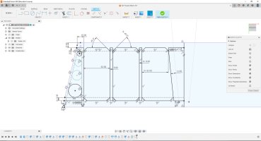
H5- Here I have used the trim tool to go in and cut away all the lines I don't want any more.
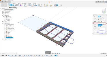
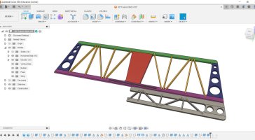
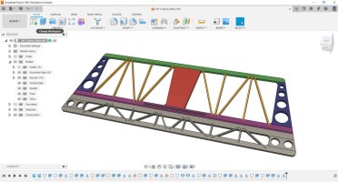
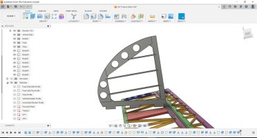
H6- Lastly to finish up the sketch lets add some lighten holes in the tip portion. This isn't needed but I like to save weight everywhere possible.
 

Attachments

  • H-stab1.JPG
    H-stab1.JPG
    108.6 KB · Views: 88
  • H-stab2.JPG
    H-stab2.JPG
    115.3 KB · Views: 84
  • H-stab3.JPG
    H-stab3.JPG
    137.2 KB · Views: 93
  • H-stab4.JPG
    H-stab4.JPG
    154.9 KB · Views: 133
  • H-stab5.JPG
    H-stab5.JPG
    144.9 KB · Views: 87
  • H-stab6.JPG
    H-stab6.JPG
    153.2 KB · Views: 88

BalsaDust

Moderator
Note that I have only been drawing one half of the stab the entire time.

H7- Lets start making actual parts. Use the extrude tool to extrude the LE and TE parts and set to new body.
H8- Remember after the first extrude Fusion will automatically turn the sketch off so we need to go back and turn it back on. This is where fusion gets fun in how it does some things. You can no select and extrude the tip, center section, and both sticks all at once and say new body.
H9- Here you can see that I have only used the extrude tool twice yet it created 6 new extrusions for me. Note I have created a new folder under my bodies tab for the stab parts. Go ahead and move them all in there.
H10- Looky there we now have an almost complete stab. I just used the mirror tool to do this. You can see in the history bar at the bottom I had to do this 3 times so I will explain. First I turned off the visabilty of the tip, center, and sticks leaving just the LE and TE. I mirror them and use the join command. Then I turn those off and turn back on the center section and do the same thing. lastly you can turn everything back on and mirror just the 2 sticks and the tip but use new body instead of join.
H11- Now for some fun. This step isn't required but it makes it easier to see how parts fit together. If you just type the letter A it will bring up the appearance tab and here you can go through the endless amounts of choices to make it look however you would like.
H12- Last step is we need to bevel the TE. I created a sketch of the center workplane. I decided for simplicity to just bevel the edge but you could very easily draw it as a seperate piece of tristock as well.
 

Attachments

  • H-stab7.JPG
    H-stab7.JPG
    145.1 KB · Views: 90
  • H-stab8.JPG
    H-stab8.JPG
    173.8 KB · Views: 91
  • H-stab9.JPG
    H-stab9.JPG
    138.3 KB · Views: 116
  • H-stab10.JPG
    H-stab10.JPG
    134 KB · Views: 92
  • H-stab11.JPG
    H-stab11.JPG
    170.8 KB · Views: 115
  • H-stab12.JPG
    H-stab12.JPG
    174.3 KB · Views: 89

BalsaDust

Moderator
So change of plans on the stab. Decided it would be better if it was done more truss like. Was easy enough. Just deleted the mirrors and extrusions and modified my original sketch.
8EECF255-F241-406C-9553-2AF397EE9D29.jpeg
 

BalsaDust

Moderator
Lets do the elevator next. Its basically a repeat of the stab itself.
 

Attachments

  • ELE1.JPG
    ELE1.JPG
    134.6 KB · Views: 84
  • ELE2.JPG
    ELE2.JPG
    197.9 KB · Views: 86
  • ELE3.JPG
    ELE3.JPG
    171.3 KB · Views: 115
  • ELE4.JPG
    ELE4.JPG
    185.6 KB · Views: 85
  • ELE5.JPG
    ELE5.JPG
    198.7 KB · Views: 87
  • ELE6.JPG
    ELE6.JPG
    151.1 KB · Views: 88

BalsaDust

Moderator
Here is the vertical stab and the rudder. Rinse and repeat of how I did the horizontal. Will try to start on the fuse in the next couple of days at which point I can introduce a couple of new tools.
 

Attachments

  • Vertical1.JPG
    Vertical1.JPG
    174.7 KB · Views: 105
  • Vertical2.JPG
    Vertical2.JPG
    167.6 KB · Views: 86
  • Rudder1.JPG
    Rudder1.JPG
    160.2 KB · Views: 83
  • Rudder2.JPG
    Rudder2.JPG
    164.2 KB · Views: 92
  • Tail parts.JPG
    Tail parts.JPG
    196.8 KB · Views: 90

BalsaDust

Moderator
Lets design a fuse.
1. We will use a new tool which is the shell command. Once selected you will first select any face on the solid body you want to go away and you have to pick at least one face so it knows which solid to shell. For the fuse I want the wing saddle area and the firewall to go away. A box will pop up asking for what thickness you want to go with. For this I'm going with 2mm.
2. you can see the faces I selected are gone and the fuse has been hollowed out.
3. Sketch on the nose to draw out the firewall.
4. Extrude it creating a new body.
5. before we get into the formers sketch on the bottom of the fuse and do a cutout for where the H stab sits.
6. The cutout
 

Attachments

  • 1.JPG
    1.JPG
    131.1 KB · Views: 104
  • 2.JPG
    2.JPG
    127 KB · Views: 102
  • 3 Firewall.JPG
    3 Firewall.JPG
    185.2 KB · Views: 84
  • 4 Firewall.JPG
    4 Firewall.JPG
    144.6 KB · Views: 81
  • 5 tail cutout.JPG
    5 tail cutout.JPG
    239.7 KB · Views: 87
  • 6 tail cutout.JPG
    6 tail cutout.JPG
    168.5 KB · Views: 84

frydaddy08

New to GSN!
Thanks for doing this BD, it helps a lot. I've been going with YT vids from different people to get ideas on how to use the different 'commands' and different ways to approach the same outcome.
Would like to see you continue this as it is a simple design that puts all the different functions/commands together for a final result.
I have some 3-views and plans from Wylam that I want to turn into F360 drawings to build some planes that aren't that popular.
 

BalsaDust

Moderator
Thanks for doing this BD, it helps a lot. I've been going with YT vids from different people to get ideas on how to use the different 'commands' and different ways to approach the same outcome.
Would like to see you continue this as it is a simple design that puts all the different functions/commands together for a final result.
I have some 3-views and plans from Wylam that I want to turn into F360 drawings to build some planes that aren't that popular.
Yeah I need to finish it up as I would love to be able to share the project with anyone that would like to build it. Just been preoccupied with other stuff.
 
Top