AKNick
640cc Uber Pimp
Reviving an OLD Thread.
There are a lot of Anti-Spark plugs out these days and not a whole lot of explanation of how they work. I have made a JST connector with a resistor to it, I'd plug the JST connector and then the battery connector, then unplug the JST circuit (didn't really have to it just made me feel better). BUT with the new connectors available I don't have to make these hokey connectors.
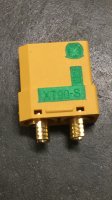
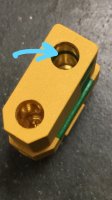
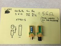
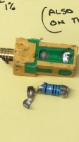
AMASS XT90-S connectors have been my go to these days for my 6S batteries and 12S setups. The way they war are similar to how my old method but the resistor is integrated into the connector housing. The XT90-S uses a 5.6 Ohm 1 Watt Resistor on the positive receptacle on the battery side.... jerks designed this so you have to pay extra verses putting it on the ESC only.
https://hobbyking.com/en_us/xt90-s-...VTD6tBh1-Ig-EEAQYASABEgJbGvD_BwE&gclsrc=aw.ds
How it works? The resistor circuit makes first contact/connection when inserting the connector, and when fully inserted it bypasses this circuit by providing an interrupted connection separate of the resistor - electricity then knows where to go for the path of least resistance.
I'll add some pictures with some exploratory surgery too:


