• If you are new to GiantScaleNews.com, please register, introduce yourself, and make yourself at home.

    We're 1st in Giant Scale RC because we've got the best membership on the internet! Take a look around and don't forget to register to get all of the benefits of GSN membership!

    Welcome!

IMAC JTEC MX2 3.1 Build by Terry P

oh58skid

50cc
Friday I picked up the MX2 3.1 kit from Al and Kevin at the Wram show. I have built two Extra 300 3.1 CS....one I am currently flying in Intermediate and the other one is ready for covering and paint and hopefully will be ready as a back up for this upcoming IMAC season.
The Mx will be set up with a DA 170 and Jtec HP 90 pipes, and JR 8711 servos. I will be posting pics as I progress with the build.
 

oh58skid

50cc
OK Guys here we go.......
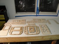
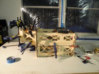
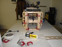
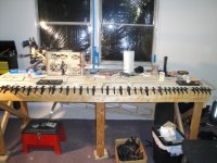
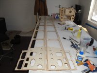
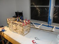
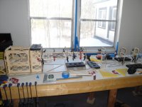
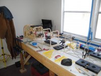
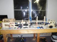
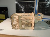
I gathered up all of the motor box parts and dry fit them together first to check the fit before gluing. All of the parts fit perfectly and tight. The motor box is self aligning so no jigs are needed for the assembly. Before final glue up of the motor box make sure the left motor box side is on the left and the right is on the right......if not you will have left engine thrust, which is not a good thing !
The 1/4 and 1/8 inch firewall plates need to be laminated together before starting final assembly of the motor box.
After letting the firewall setup for a short period the motor box was then assembled using Hysol 9462, it was then clamped together and put aside to cure.
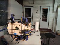
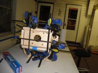
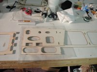
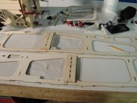
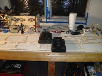
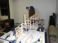
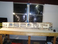
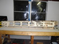
Next the fuse sides where joined together, there is a doubler that is added where the two fuse sides join, you can use F5 to align the doubler to the sides. Also there is a doubler that is added to the fuse sides at the tail. Two 3/8 x 3/8 pieces of balsa stock need to be spliced together to make up a top and bottom longeron. After making up the fuse sides I then glued the fuse top to the top of the motor box, again the fuse top is tabbed to align with the motor box so its all self aligning. The motor box and fuse top is then turned upside down on the build table for the rest of the assembly. Next I used servo screws to secure the fuse top and motor box to the build table. The remaining formers and servo trays are then glued to fuse top. The fuse sides are then dry fit to make sure there are no problems before final assembly to the motor box and fuse top. After encountering no issues with the fit of the fuse sides it was time to gather up a lot of clamps and the Hysol EHP20. The fuse sides are then assembled and left to cure , then tail post and 1/4 bottom stringers are glued on.
 

Attachments

  • DSC01319.JPG
    DSC01319.JPG
    139.9 KB · Views: 590
  • DSC01320.JPG
    DSC01320.JPG
    137.1 KB · Views: 510
  • DSC01321.JPG
    DSC01321.JPG
    144.2 KB · Views: 595
  • DSC01322.JPG
    DSC01322.JPG
    136.1 KB · Views: 493
  • DSC01323.JPG
    DSC01323.JPG
    140 KB · Views: 537
  • DSC01324.JPG
    DSC01324.JPG
    136.4 KB · Views: 522
  • DSC01325.JPG
    DSC01325.JPG
    137.2 KB · Views: 501
  • DSC01326.JPG
    DSC01326.JPG
    135.6 KB · Views: 502
  • DSC01327.JPG
    DSC01327.JPG
    139 KB · Views: 488
  • DSC01328.JPG
    DSC01328.JPG
    142.3 KB · Views: 499
  • DSC01329.JPG
    DSC01329.JPG
    142.3 KB · Views: 489
  • DSC01330.JPG
    DSC01330.JPG
    140.3 KB · Views: 407
  • DSC01331.JPG
    DSC01331.JPG
    140.1 KB · Views: 504
  • DSC01332.JPG
    DSC01332.JPG
    138.8 KB · Views: 530
  • DSC01333.JPG
    DSC01333.JPG
    138.7 KB · Views: 530
  • DSC01334.JPG
    DSC01334.JPG
    136.4 KB · Views: 502
  • DSC01335.JPG
    DSC01335.JPG
    140.5 KB · Views: 583
  • DSC01336.JPG
    DSC01336.JPG
    140.4 KB · Views: 494

stangflyer

I like 'em "BIG"!
OK Guys here we go.......
I gathered up all of the motor box parts and dry fit them together first to check the fit before gluing. All of the parts fit perfectly and tight. The motor box is self aligning so no jigs are needed for the assembly. Before final glue up of the motor box make sure the left motor box side is on the left and the right is on the right......if not you will have left engine thrust, which is not a good thing !
The 1/4 and 1/8 inch firewall plates need to be laminated together before starting final assembly of the motor box.
After letting the firewall setup for a short period the motor box was then assembled using Hysol 9462, it was then clamped together and put aside to cure.
Next the fuse sides where joined together, there is a doubler that is added where the two fuse sides join, you can use F5 to align the doubler to the sides. Also there is a doubler that is added to the fuse sides at the tail. Two 3/8 x 3/8 pieces of balsa stock need to be spliced together to make up a top and bottom longeron. After making up the fuse sides I then glued the fuse top to the top of the motor box, again the fuse top is tabbed to align with the motor box so its all self aligning. The motor box and fuse top is then turned upside down on the build table for the rest of the assembly. Next I used servo screws to secure the fuse top and motor box to the build table. The remaining formers and servo trays are then glued to fuse top. The fuse sides are then dry fit to make sure there are no problems before final assembly to the motor box and fuse top. After encountering no issues with the fit of the fuse sides it was time to gather up a lot of clamps and the Hysol EHP20. The fuse sides are then assembled and left to cure , then tail post and 1/4 bottom stringers are glued on.
Really nice! I really need to get back into building. I am starting to miss all the fitting and gluing things together to make a flying beauty.
 

Pistolera

HEY!..GET OUTTA MY TREE!
Looks like a much lower wing position than the 300, at least from what I can tell by the pics?
 
Top