• If you are new to GiantScaleNews.com, please register, introduce yourself, and make yourself at home.

    We're 1st in Giant Scale RC because we've got the best membership on the internet! Take a look around and don't forget to register to get all of the benefits of GSN membership!

    Welcome!

Scale RCM 1/3 Scale Champ Build

TonyHallo

150cc
Cut a hole in the firewall for the carburetor and velocity stack. The instruction manual warns against operating without the velocity stack as it will effect performance, my ram pipe information indicates the shape they selected will decrease performance by 1.2% to 5%. The shape is similar to 4 and 5 below but not quite curved as 10. I will run the engine with and without the velocity stack, I believe 11 would work the best in my case.
IMG_2379.JPG
Velocity Stack Designs.jpg
 

TonyHallo

150cc
The throttle and choke servos are mounted in a removable tray on the back of the box. Four servo screws hold the tray in place so that the servo can be placed if the need arises. Unbolt the throttle and choke ball links, remove four screws and slide the tray out.

IMG_2380.JPG


IMG_2382.JPG
 

Snoopy1

640cc Uber Pimp
Nice clean installation easy to maintain.
Hope the area left between the ram pipe and the box is enough. With out crunching some numbers but from experience the air has to go down the box and reverse direction into the carburetor. Friction from box walls and the pinching of the air going around the end of the ram pipe is a pinch point. My guess would be at least 2 times area of top of the ram pipe. And the back face of the box should be one times the diameter of the ram tube inlet. This just from my experience in setting up racing engines in confined spaces. Please not just trying to help.
Looking at the pictures again it would be very interesting to see how the performance would be if you change nothing but just removed the ram air tube.
 
Last edited:

TonyHallo

150cc
The inlet diameter of the ram is 1.25", there's about 1 1/2" from inlet of the ram to the back wall. The box area is 6.9 sq. inches, area of ram pipe is 1.23", the ram and the carb are about the same area so there is about 4 1/2 times free area to that of the pipe. I was erring on the side of caution when I sized the box (I Hope!). I don't expect to be at full throttle very often anyway. I have the radio on the Cherokee set to 60% of full throttle and rarely open it all the way. I believe scale planes should be flown in a scale manner, long roll outs, low climb rate and the like.
I'll take any help.
Thanks
 

Snoopy1

640cc Uber Pimp
The inlet diameter of the ram is 1.25", there's about 1 1/2" from inlet of the ram to the back wall. The box area is 6.9 sq. inches, area of ram pipe is 1.23", the ram and the carb are about the same area so there is about 4 1/2 times free area to that of the pipe. I was erring on the side of caution when I sized the box (I Hope!). I don't expect to be at full throttle very often anyway. I have the radio on the Cherokee set to 60% of full throttle and rarely open it all the way. I believe scale planes should be flown in a scale manner, long roll outs, low climb rate and the like.
I'll take any help.
Thanks
Looks like you have all the bases covered.
 

Alky6

150cc
Cut a hole in the firewall for the carburetor and velocity stack. The instruction manual warns against operating without the velocity stack as it will effect performance, my ram pipe information indicates the shape they selected will decrease performance by 1.2% to 5%. The shape is similar to 4 and 5 below but not quite curved as 10. I will run the engine with and without the velocity stack, I believe 11 would work the best in my case.View attachment 109391 View attachment 109392
Could be more of a pulse tuning issue they have to deal with across the rpm range versus a reduction in friction on flow. Purely speculation.
 

49dimes

Damn I'm hungry
It's hard for the pumper style carbs to deliver a steady flow of fuel because they are being "pulsed" by pressure being developed on the top of the piston through the intake valve. Lends them to easily "Load Up" at idle and run lean at WOT.
 

TonyHallo

150cc
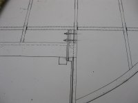
I was never crazy about the aileron hinges shown on the plans, a piece of 1/16 aluminum sheet running on a 4-40 screw, just seemed that these would develop slop in short order. About a week ago was reading a post on how to install C. B. Associates strap hinges and I remembered that I had won a package of these as a door prize some 30 years ago. I found three of them in my hinge drawer, yes I keep them all these years! Got to looking and decided that the straps would make a much better hinge. The straps are glass filled, the knuckle is 1/4" in diameter, 1/4" long, bushed with a 9/32" piece of brass tube, the hinge pin is 1/8" brass tube. I was 1 strap short but MECOA K&B has bought the line and continues to supply them, in shipping as I write. The plan hinge is shown below.

IMG_2240.JPG
 

TonyHallo

150cc
The hinge brackets are milled from aluminum bar with 1/8" brass pin, the cotter pin is from a DuBro giant scale hinge. I was planning to use a 4-40 clevis on the original but elected to use a heavy duty ball link. I'm happy that I made this modification.

IMG_2384.JPG
 

TonyHallo

150cc
It's hard for the pumper style carbs to deliver a steady flow of fuel because they are being "pulsed" by pressure being developed on the top of the piston through the intake valve. Lends them to easily "Load Up" at idle and run lean at WOT.

The venturi is rather small on the carburetor, looks like something from a 30 CC string line trimmer. I guess it has to handle 42 1/2 cc per revolution. When I look at the carburetor it is hard the image this engine will swing a 25"-27" propeller. we shall see. I'm guessing the small venturi is need to develop sufficient pressure pulses? Can you explain why it loads at idle?
 
Top