• If you are new to GiantScaleNews.com, please register, introduce yourself, and make yourself at home.

    We're 1st in Giant Scale RC because we've got the best membership on the internet! Take a look around and don't forget to register to get all of the benefits of GSN membership!

    Welcome!

Redundant Receiver Installation

JimD

50cc
When we started flying giant scale airplanes with big (85cc) gas engines and AUW of 40-45lbs, how to decrease the chance for radio failure was on our mind. First, there is the vibration, then there are the large servos and high current demands.

Looking for a way to use the equipment I already had invested in and trusted for 1/4-scale glow engine planes, we came up with the idea of using redundant receivers. I personally like the way the Futaba 10C transmitter fits my hands and having come up through the mid price range line of Futaba computer radios, the programming was very familiar.

Multiple 2.4GHz Futaba receivers can be bound to the 10C transmitter on one model setting with no problems. As far as the receivers are concerned, they are working independently and don't know there is another one right beside it getting the same information from the transmitter.

Our Pilatus Porter has the following: 2-aileron servos, 2-elevator servos, 2-flap servos, 1-rudder servo, 1-tail wheel servo, 1-throttle servo, 1-choke servo, and 1-tow release servo. Eleven in total and all are Hitec HS-5645MG servos.

The first receiver operates the right aileron servo, the left flap servo, the left elevator servo, the rudder servo, and the throttle servo. Five in total.

The second receiver operates the left aileron servo, the right flap servo, the right elevator servo, the tail wheel servo, the choke servo, and the tow release servo. Six in total. (unlike the throttle servo, the choke and tow release servos do not get activated as often)

Neither receiver has a high servo count as would be the case with a single receiver setup.

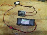
Each receiver has its own battery pack and switch harness. The switch harness is an Electro Dynamics HD Ultra Switch with 18AWG input and dual 22AWG outputs. The battery to switch connector is a high current red Deans. Bottom line, this setup can supply large amounts of current to the receiver and spread the load across the bus bar of the receiver by attaching at two locations.

We were using 4000mAh NiMH battery packs but switched to 2500mAh A123 packs this year.

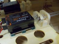
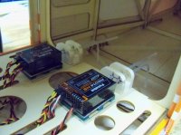
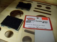
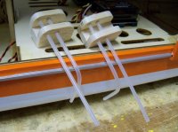
As for the vibration issue, we used Kyosho Vibration Absorbing material under our receiver mounts. A piece of 1/32" plywood with a Velcro pad is attached to the Kyosho material and the receiver is then attached to this with Velcro. We made tubes to direct the antennas at 90 degrees to each other and attached them to the receiver tray.

We have now flown hundreds of hours with this setup in multiple airplanes and it has been rock solid across the board! Unfortunately, the new Futaba 14SGA using telemetry does not allow this type installation.

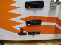
Here is a picture essay of the final product:
101.JPG 102.JPG 103.JPG 104.JPG 105.JPG 106.JPG
 

JimD

50cc
Hey Thurmma, that's great! :too-cool:

It may be low tech, but I really like the simplicity of it. This offers a way to get into giant scale without having to learn about power expanders, redundant batteries, and other high tech electronic gadgets. Builder can use what is already on hand and familiar.

The current generation of computer radios with telemetry are addressing these new issues of high voltage and high current and at some point we will be moving on to this next generation. In the mean time, this setup has been providing a good solid solution to my giant scale needs.
 

JimD

50cc
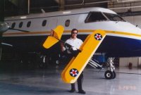
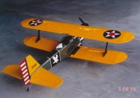
The first time I tried this was back in the 72MHz days. I put redundant receivers in a scratch built 1.33% enlargement of the Sig Hog Bipe. I thought it was a big airplane at the time (completed build February, 1998). It was converted to 2.4GHz several years ago and continues to look fantastic in the air.
101.JPG 102.JPG 103.JPG 104.JPG 105.JPG 106.JPG
 
When we started flying giant scale airplanes with big (85cc) gas engines and AUW of 40-45lbs, how to decrease the chance for radio failure was on our mind. First, there is the vibration, then there are the large servos and high current demands.

Looking for a way to use the equipment I already had invested in and trusted for 1/4-scale glow engine planes, we came up with the idea of using redundant receivers. I personally like the way the Futaba 10C transmitter fits my hands and having come up through the mid price range line of Futaba computer radios, the programming was very familiar.

Multiple 2.4GHz Futaba receivers can be bound to the 10C transmitter on one model setting with no problems. As far as the receivers are concerned, they are working independently and don't know there is another one right beside it getting the same information from the transmitter.

Our Pilatus Porter has the following: 2-aileron servos, 2-elevator servos, 2-flap servos, 1-rudder servo, 1-tail wheel servo, 1-throttle servo, 1-choke servo, and 1-tow release servo. Eleven in total and all are Hitec HS-5645MG servos.

The first receiver operates the right aileron servo, the left flap servo, the left elevator servo, the rudder servo, and the throttle servo. Five in total.

The second receiver operates the left aileron servo, the right flap servo, the right elevator servo, the tail wheel servo, the choke servo, and the tow release servo. Six in total. (unlike the throttle servo, the choke and tow release servos do not get activated as often)

Neither receiver has a high servo count as would be the case with a single receiver setup.

Each receiver has its own battery pack and switch harness. The switch harness is an Electro Dynamics HD Ultra Switch with 18AWG input and dual 22AWG outputs. The battery to switch connector is a high current red Deans. Bottom line, this setup can supply large amounts of current to the receiver and spread the load across the bus bar of the receiver by attaching at two locations.

We were using 4000mAh NiMH battery packs but switched to 2500mAh A123 packs this year.

As for the vibration issue, we used Kyosho Vibration Absorbing material under our receiver mounts. A piece of 1/32" plywood with a Velcro pad is attached to the Kyosho material and the receiver is then attached to this with Velcro. We made tubes to direct the antennas at 90 degrees to each other and attached them to the receiver tray.

We have now flown hundreds of hours with this setup in multiple airplanes and it has been rock solid across the board! Unfortunately, the new Futaba 14SGA using telemetry does not allow this type installation.

Here is a picture essay of the final product:
View attachment 9981 View attachment 9982 View attachment 9983 View attachment 9984 View attachment 9985 View attachment 9986

What receivers do you use and do you use a "Y" for the elevator servos?
 

JimD

50cc
You cannot use a Y harness, because there can be no electrical connection between the two receivers.

There are several ways to do this:

The easy way is to use the AILVATOR mixing function in your transmitter. Plug one elevator servo into receiver A channel #2 and the other elevator servo into receiver B channel #8. This allows independent end point adjustment, sub trim adjustment, and direction of rotation settings for each servo by way of the transmitter.

Another easy way is to use programmable servos, like the Hitec HS -7954SH or HS-7955TG. Servos plug into receiver channel #2 in both receiver A and receiver B. End points, centering, and direction of rotation are set by way of a servo programmer.

I thought that was what you are doing as you only have 10 channels available!! Thanks for explaining how you did it.
 

Wacobipe

100cc
This is a question that has confused me for some time so this provides me a perfect opportunity to try to better understand. I totally understand the setup...what I don't understand is that in the event of a receiver failure you end up with a 1/2 controllable aircraft, which seems to me not much better than one with no control and in fail safe mode. I can't believe either one is coming home in one piece...am I wrong?

I fly JR and now use their Powersafe receiver which takes 2 separate battery inputs directly into the receiver. I use no switches, and just plug/unplug batteries every flight. This provides no redundancy if the one and only receiver fails, but is as redundant as I can get without a drastically larger investment and a lot more electronics (that could fail).

This is an interesting topic and one I've never found a suitable solution to...so I am hoping to learn here.
 

JimD

50cc
Wacobipe...Failure is always a possibility...that said, is there any way of decreasing the possibility of catastrophic failure?

After four plus decades of flying R/C, the failures I have witnessed (discounting pilot error) are either some type of power failure or some type of signal reception failure.

Having two batteries and two receivers seemed like a simple way to address these points of failure back in 1998...fortunately, I never had to test the ability of the plane to fly on just one receiver.

One of the reasons I decided to stay with this system for my giant scale 2.4GHz setups was the "brown out" issue that seemed to be an problem early on. By limiting the number of servos attached to the receiver, we reduced the amount of total maximum current draw and subsequent voltage drop thus decreasing the possibility of a brown out. (BTW, I make no claim of being an electronics wizard, just trying to state what seemed apparent to me) Another thing we did was to put the throttle on one receiver and the choke on the other so in the event of a receiver failure the engine could be shut down either by throttle or by choke.

As I stated at the outset, this is a low tech way. The PowerSafe receiver system does these things in a more high tech way and I like what they have done with this design.

As for controlling a plane with one elevator, and/or one aileron, or rudder and no ailerons...I have done this because of servo failures and/or control surface structural failures. It is amazing what will fly, imperfectly for sure, but still fly and make it back to the runway. Teaching beginners to fly (and flying the planes they constructed) gave us plenty of unexpected moments. If you want to sharpen your reflexes, spend some time on a trainer cord!
 
Top