JimD
50cc
When we started flying giant scale airplanes with big (85cc) gas engines and AUW of 40-45lbs, how to decrease the chance for radio failure was on our mind. First, there is the vibration, then there are the large servos and high current demands.
Looking for a way to use the equipment I already had invested in and trusted for 1/4-scale glow engine planes, we came up with the idea of using redundant receivers. I personally like the way the Futaba 10C transmitter fits my hands and having come up through the mid price range line of Futaba computer radios, the programming was very familiar.
Multiple 2.4GHz Futaba receivers can be bound to the 10C transmitter on one model setting with no problems. As far as the receivers are concerned, they are working independently and don't know there is another one right beside it getting the same information from the transmitter.
Our Pilatus Porter has the following: 2-aileron servos, 2-elevator servos, 2-flap servos, 1-rudder servo, 1-tail wheel servo, 1-throttle servo, 1-choke servo, and 1-tow release servo. Eleven in total and all are Hitec HS-5645MG servos.
The first receiver operates the right aileron servo, the left flap servo, the left elevator servo, the rudder servo, and the throttle servo. Five in total.
The second receiver operates the left aileron servo, the right flap servo, the right elevator servo, the tail wheel servo, the choke servo, and the tow release servo. Six in total. (unlike the throttle servo, the choke and tow release servos do not get activated as often)
Neither receiver has a high servo count as would be the case with a single receiver setup.
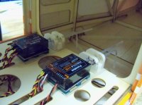
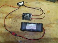
Each receiver has its own battery pack and switch harness. The switch harness is an Electro Dynamics HD Ultra Switch with 18AWG input and dual 22AWG outputs. The battery to switch connector is a high current red Deans. Bottom line, this setup can supply large amounts of current to the receiver and spread the load across the bus bar of the receiver by attaching at two locations.
We were using 4000mAh NiMH battery packs but switched to 2500mAh A123 packs this year.
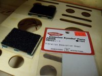
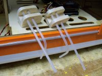
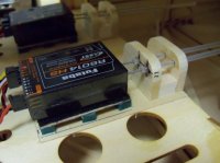
As for the vibration issue, we used Kyosho Vibration Absorbing material under our receiver mounts. A piece of 1/32" plywood with a Velcro pad is attached to the Kyosho material and the receiver is then attached to this with Velcro. We made tubes to direct the antennas at 90 degrees to each other and attached them to the receiver tray.
We have now flown hundreds of hours with this setup in multiple airplanes and it has been rock solid across the board! Unfortunately, the new Futaba 14SGA using telemetry does not allow this type installation.
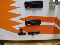
Here is a picture essay of the final product:


