• If you are new to GiantScaleNews.com, please register, introduce yourself, and make yourself at home.

    We're 1st in Giant Scale RC because we've got the best membership on the internet! Take a look around and don't forget to register to get all of the benefits of GSN membership!

    Welcome!
  • Unless you are a paid advertiser NO more posting advertisement in the individual vendor forums. You may post in the Manufacturer's Announcements section only but only ONCE a month unless your a paid advertiser.

GWS P-38 Build Log and Review

rcdude07

70cc twin V2
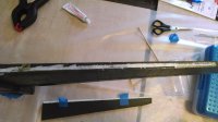
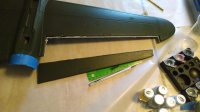
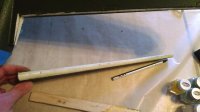
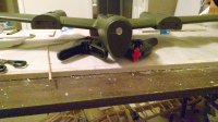
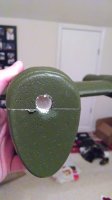
Saturday was build day #1 for me. Steps were straight forward for a while: glue the wing halves to the main wings, glue the wing spars in place, cut the ailerons out, sand the ailerons LE. I learned here that even blue painter's tape will pull of some of the green finish from the foam no matter how light the tape was applied. Both spars were a little longer than the precut channel so I had to lengthen the channels some. It may be due to this reason the rear spar did not seat flat/flush like it should have and is sticking out a tiny bit. The date on the kit is showing again as all spars are fiberglass instead of carbon fiber. Then came a little beef with the instructions. After cutting the ailerons out, they have you marking the hinge locations on the ailerons, then sanding. Well, this foam (EPO I think) sands faster than soft balsa, so so after shaping the aileron LE, the hing marks were gone, so I had to remark. Also, it's very tough to mark the center of the ailerons since it's preshaped and then having to cut off the aileron from the wing. So I had to eyeball it. Sure, if you have 4 hands you could rig something up to measure and mark the center line. Also, there is no mention of cleaning up the wing TE from cutting the ailerons off. So I took it upon myself to smooth the cuts on the wing. After doing this the manual calls for permanently attaching hinges and control horn, since I plan to paint the belly, I skipped this and moved on to gluing the nuts in place in under the super charger and what apparently will be boom pod alignment pieces. Again, I had a beef with the manual in not having clear pictures as to how these plastic pieces should face. Fortunately a quick Google search showed the boom nut, and going forward in the manual showed another plastic piece going on the boom that coincides with this piece (of course I found all this information before gluing in place). Since I didn't have my paints I couldn't paint the clear nose cone, instead I drilled the air holes in the nose and fuse, per instructions. 3mm holes are drilled in all 5 of the gun hole slots on the plastic piece and a 10mm hole is drilled in the foam. The steps in the manual are clearly for the older style 1 ESC to NiMH/NiCd and all electronics in the nose. After completing this step, I came to a halt. Without my ESCes here, I can't check how they'll fit in the booms. As boom assembly is next.

I have learned this foam sands quicker than balsa, and dents easier than balsa. My right aileron TE is already looking a little war battered.

My headsuprc order arrived Saturday, so that was exciting (2 lipos, the battery y-cable, and a servo y-cable).

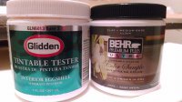
Hopefully today my ESCes from Hobby Express will show up. Tonight I'll mess with some paints my buddy loaned me. I think the green will be super close, if not I may just go with it and do a green type of camo pattern or a light coat on all the green foam.
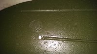
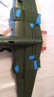
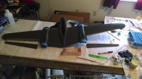
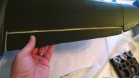
cutSparChannel.jpgrearSparIn.jpgbothAileronsCutAndSanded.jpgTestFittingAileron.jpgwingeTEhingesMarked.jpgaileronCutOut.jpgaileronLEsandedToShape.jpgbatteryCoolingHole.jpg
 

rcdude07

70cc twin V2
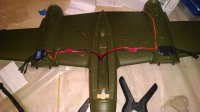
ESCes arrived yesterday. Looks like I'll be attaching them underneath the wing. The battery leads and battery y-cable are not long enough to put the ESCes in the nacelles. Also, it would appear the GWS motor connectors are not the advertised 3.5mm size, as they don't fit into the 3.5mmm connectors on the eRC ESCes I ordered. I don't think I'll get away with ordering 2 more cables for this plane, so I have to come up with another solution. DUH! Direct solder.

I'm also thinking based on my research that the stock 8x4.3 props aren't going to make me happy flight wise. But we'll see.

Played with my buddy's paints last night. The green that matches his HH Spitfire is a bit lighter than the green on my foam. It's easily detectable in direct light, but not so much in the dark. I'm not a fan of mixing colors, but I may try to tonight/today if I get time.
 
Last edited by a moderator:

rcdude07

70cc twin V2
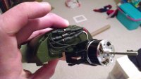
Put another coat of black on the super chargers last night. Brushing it on the inside of the plastic to protect the paint. I also spent some time testing the motor mount, motor, wiring, and ESC placements. My solution is going to use the supplied motor wire extensions, use the bullet connectors here covered with heat shrink, then solder the ESC to the wire extension, and mount the motor wires such as the bullet connectors are accessible in the cowls in case I get a counter rotating prop and want to add the scale/coolness factor. The ESCes will be mounted under the wing either recessed in a little or just double sided taped on around the side of the fuse.

Opinion needed people: since this plane is not designed to be taken apart for transport, would you paint it now, or wait until it's together and fight around the wiring jobs and electronics? I'm leaning towards painting now.

Tonight I teach Royal Ambassadors at church, then Survivor (yes, I still watch it), and tomorrow is Big Bang Theory. So it'll be Friday at the earliest before I'm back at the workbench.

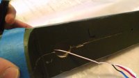
IMG_20140304_203940151.jpg going to try to put the motor wires like this to have access to the bullet connectors. Tape or hot glue to hold the wires in place


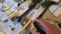
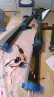
IMG_20140304_203352621.jpg ESC battery leads are not long enough to go to the nacelles/booms


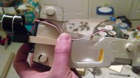
IMG_20140304_203930365.jpg test fitting motor mount, motor, and motor extensions. Going to have to carve the channel out deeper for the wire to fit. Can't go through the top as that's where the boom alignment piece goes.
Click image for larger version.

IMG_20140303_202926620.jpg testing the green my friend is letting me use. Lighter in shade. Spent hours searching for camo schemes and none had a two tone green pattern. Looks like the entire plane will get a coat as this is not quite close enough for the nose, cowls, pods, control surface LE, and touch ups.

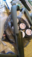
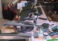
IMG_20140303_211139758.jpg these paints my buddy had custom matched for his PZ birds at Home Depot. So far are proving to be foam safe. Going to use one of his greys for the bottom.
 

rcdude07

70cc twin V2
Big update today!!!


Friday night: first coat of light gray was brushed on everything. I used a 2" brush. The foam absorbed a lot of the paint and the green on the foam had me regretting this decision.

Saturday morning: Second coat of gray was brushed on. Now it looks good and I'm not regretting the choice.

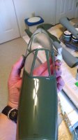
Saturday afternoon: first, and only coat of green was brushed on everything. After it dried the CS was looking niiiiice and scale-ish. I painted on the inside of the plastic pieces so the paint doesn't scratch/wear off easily. Also bound the AR400 to the DX8. Also soldered the motor wire extensions to the ESCes. Thought I followed the same pattern on each setup, but alas I found I did not. So at least 1 motor will spin backwards initially.

Sunday morning: programmed the ESCes individually.

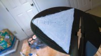
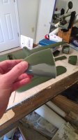
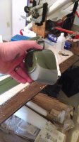
Sunday afternoon: painted the white triangle squadron symbol on the vertical fins (scale markings and a great orientation marking), glued the nose cone on, glued in the fiberglass supports and motor mounts in the booms, modified the motor wire extension channel in the booms, glued the booms together, glued the hinges into the wing.


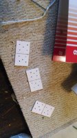
IMG_20140309_143207888.jpg holes to help glue soak through the hinges and adhere to the foam. A member on a different forum suggested this from his experience with GWS kits.

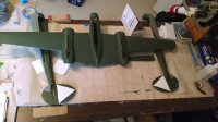
IMG_20140309_134052869.jpg scale squadron marking that serves double as an orientation marking. hand brushed with Testors flat white acrylic paint.

IMG_20140308_140923176.jpg IMG_20140309_140010755.jpg IMG_20140308_140933234.jpg IMG_20140308_140941376.jpg

IMG_20140309_135444434.jpg modified wire channel cut in each half of the booms. Doing so allows me to move the wire back and forth to get slack as needed. Should also help in the future if I need to change out the wire.

IMG_20140308_125101164.jpg IMG_20140309_141946454.jpg IMG_20140309_130101208.jpg IMG_20140308_140913159.jpg
 
Last edited by a moderator:

rcdude07

70cc twin V2
I have to admit I had my doubts about the GWS glue and the hinges. But after 24 hours, the hinges were in the wing and weren't budging when I tried to wiggle them. The manual says to glue half into the wing and wait for glue to dry. No indications of how long this would take, so I did the wiggle/light tug test every couple of hours and in the morning to see how the glue was setting.

Last night the ailerons got glued onto the hinges, the boom alignment plates were glued in, glued in some plastic cups that are for holding the screws in that attach the booms to the wing, and a 4th and final coat of flat white applied to the triangles. When gluing the ailerons to the hinges I made sure to use a knife to wipe away the excess glue as it squeezed out of the slots as well as work the ailerons in both directions to ensure they weren't getting glued to the wings.
 

rcdude07

70cc twin V2
Last night's progress included: plastic firewalls being glued on, the plastic horizontal stab support/install pieces being glued on, and cutting a V into the foam on the boom where it sits in the wing (I assume this is to help with wire routing later).
 
Top