• If you are new to GiantScaleNews.com, please register, introduce yourself, and make yourself at home.

    We're 1st in Giant Scale RC because we've got the best membership on the internet! Take a look around and don't forget to register to get all of the benefits of GSN membership!

    Welcome!

Scale 35% Krill Extra 330SC....CUSTOM-ARF!!!

Pistolera

HEY!..GET OUTTA MY TREE!
Time to get the saw back out and cut some more on this airplane :devil-dance:.

This is probably the farthest deviation from scale, but I decided a while ago that I would split the ailerons into 2 sections each. A couple of reasons why;
  • short "outboard" ailerons have been incorporated into the wings of many high-end IMAC planes like Cardens, etc. The theory is they tend to not disturb the airflow over the elevators in rolls and rolling circles while still giving plenty of authority for precision flying. I've flown a few and they work.
  • I still wish to retain the full ailerons (using both sections together) for more radical roll rates/3D etc.
  • The inboard sections can be used as flaps for short fields and/or approaches over treelines, etc. I've flown an Extreme Flight 104 Extra and could fly it at a fast walking speed with the flaps down, without being in a harrier
  • They can also be used in a spoiler mode to dump lift, or in a crow mode (inboards up and outboards down) for very slow vertical downlines. This was fun to play with when I had my Beast.
  • Servo matching is a thing of the past, as each servo only drives its own surface.
  • Because I can!!!!
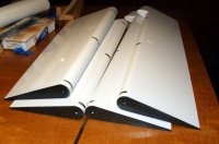
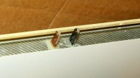
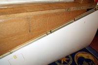
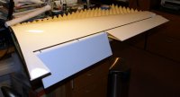
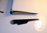
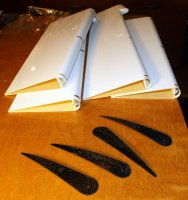
With transmitters such as my Futaba 14MZ, all these conditions can be set up fairly easily. So...after marking where I wish to separate them, I made the cuts and fabbed up some CF end plates to glue back into the now-exposed hollow ends of the shortened surfaces. I also installed an additional hinge point adjacent to the original one near the middle of the wing, so each aileron would have adequate support there.
DSC00453.jpg DSC00454.JPG DSC00452.JPG DSC00451.JPG

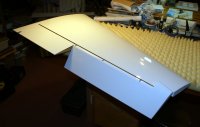
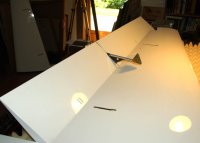
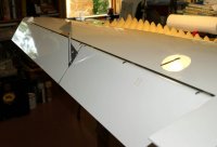
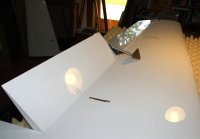
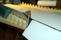
These shots show the various flight conditions;
DSC00444.JPG DSC00449.JPG DSC00450.JPG DSC00448.JPG

More to come.
 

Capt.Roll

70cc twin V2
Don't want to hijack this cool thread but just ordered an EF 104" Extra 300. Picked up nearly new R & L wings for a very attractive price. I'm going to split the ailerons but planning to make the inboard section part of the main wing.

Back on track.....Earle, where did you determine to split the ailerons? Did you go out the radius of the prop from the centerline of the fuse?
 

Pistolera

HEY!..GET OUTTA MY TREE!
Actually, I did an extreme scientific analysis......and then just looked at where the hinges were located and the chose the middle one (out of 5). Then added another hinge point beside it so the split lays between them. The custom jobs on Cardens have been done so the split (or shorty ailerons) start just outside of the elevator span. The thinking is that without the inboard aileron area disturbing flow, and therefore prop wash, it gets cleaner airflow over the whole tail group.
 

Pistolera

HEY!..GET OUTTA MY TREE!
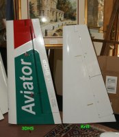
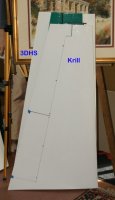
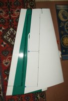
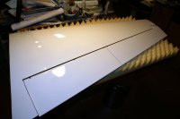
My last Extra was the awesome 3DHS 103", which I lengthened to 105" when I did the aileron counterbalances. I stood them up side by side back before I destroyed that plane last year. Interesting to see the wing area and plan form differences. The Krill is much closer to the full-scale in plan. I was surprised that the aileron area (last pic)on the Krill is about the same as the lengthened ones on the 3DHS. Damned Krill should roll fast!!!!

DSC00610.jpg DSC00611.jpg DSC00612.JPG
 

Pistolera

HEY!..GET OUTTA MY TREE!
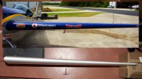
The stock control surface hinge rods are brass and all 4 weigh 100 grams. I replaced these with solid CF rods that only weigh 42 grams, even with the small aluminum grab buttons on one end. A little offset for some of the weight I've undoubted added :oblong:. The buttons BTW, go towards the fuse on the ailerons/elev, and the bottom on the rudder.
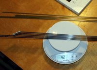
DSC02418.JPG
 

Pistolera

HEY!..GET OUTTA MY TREE!
Oh...forgot to mention if you use CF rod, You'll need to install nylon bushings in each hinge post. Easy to do, just drill out to proper size and pop them in. Otherwise the CF and phenolic post will saw against each other and they'll develop slop down the road. I cannot speak to this via experience, only what has been recommended be others doing the same mod.

Here's the bushings I used;
http://www.mcmaster.com/#7817k52/=unfi17
 

Pistolera

HEY!..GET OUTTA MY TREE!
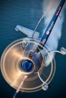
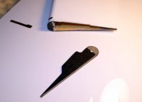
Spades.....it's what the big boys wear! :on_the_go:. You can see them hanging below each wing in this shot. They attach to the aileron and are angled forward of the hinge line so that when the aileron is deflected the triangular plate takes a "bite" into the slipstream, providing a force to help counteract the aerodynamic forces trying to push the aileron back into alignment with the slipstream. Simple but very effect.
_MG_1624small.JPG
These are another thing I've always wanted to try on an RC plane. At first I thought about just making them fixed (aligned with the slipstream), but decided that what the hell...might as well make them functional. Theoretically they should also reduce servo loading with surface deflection in the same manner they reduce stick loads for the pilot in full-scale. Although in my case they will only be effective on one section of the aileron (per side) due to the splits.

I wanted to make them removable in case they got damaged or I didn't like the effect they had on flight....but they also needed to be solidly mounted to resist aerodynamic loads. I mocked up some cardboard ones and taped in various locations, looking for a scale appearance and mounting options. Finally decided they should be attached to the outboard end of the inboard ailerons. This way I could still use full flaps and have full outboard aileron throws.

For solid yet removable mounting I cut off the CF end plate (that was previously glued) on the inboard ail. Made up a new end plate using the CF/balsa/CF laminate, with an extended mounting tab for the spade. These were then glued back into the end.
DSC01060.JPG DSC01062.JPG

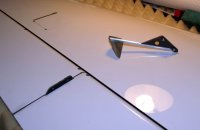
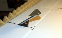
The actual spade struts are made of the same laminate with a section of streamlined aluminum strut material epoxied over it. A blind nut was epoxied into the bottom of the strut and the triangular flat plate is secured to it with a 4-40 buttonhead and an indexing pin to keep it from rotating. The whole assembly is secured to the new aileron mounting tab be two 4-40 screws which are threaded into aluminum inserts installed in the tabs. Of course these will be painted later.
DSC01075.JPG DSC01063.JPG

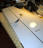
These shots show the various ranges of motion with aileron (or segment) travel.
DSC01064.JPG DSC01065.JPG DSC01067.JPG DSC01066.JPG DSC01068.JPG DSC01073.JPG

and finally, here's a head on shot of the full-scale and Krill wing.
DSC01053LR copy.jpg
 
Top