Scooterpilot
50cc
Pull-Pull Wire Explanation
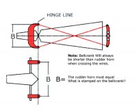
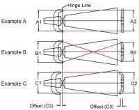
I hope this drawing and the explanations below will help you determine the which system is right for you.
Example (A) is this most perfect geometry that there is. Why, because if you look at the relationship of the bellcrank to the rudder horn and both wires, you will find that they create a perfect rectangle. Where both the bellcrank (A2) and the rudder horn (A1) are the exact same length, and both pivot on there own center line or on hinge line. The wires also are the same length in relationship to one another. With this system, whether it is SWB's or another manufactures you need to slot where the wires exits in the fuselage, as the wires should NOT touch the fuselage at anytime.
Example (B) is a whole different animal. Why, because if you look at the relationship of the bellcrank (B2) and the rudder horn (B1), you find that they are NOT the same length. The rudder horn is on Hinge line but the bellcrank is not on it's own center line. The wires however are the same length in relationship to one another. With this system, the Bellcrank (B2) is shorter with an offset to the rear of the plane. This is done to keep the wire tension as much the same as possible throughout whole spectrum of travel. This system can be used with a slot or with an single exit hole in the fuselage. If you choose to use a single exit and are using SWB's products, please contact SWB for the proper location, as where the wire exits the fuselage while the rudder is in the neutral position is NOT correct!!!
Example (C) is also good geometry. Because again if you look at the relationship of the bellcrank (C2) to the rudder horn (C1) you find that they are the same length, but this time there is a equal offset (C3) in both the bellcrank (C2) and the rudder horn (C1) in relationship to where they pivot on there own center line. The wires also are the same length in relationship to one another. With this system, whether it is SWB's or another manufactures you need to slot where the wires exits in the fuse, as the wires should NOT touch the fuselage at anytime.

![IMG_20130926_201926_640[1].jpg IMG_20130926_201926_640[1].jpg](https://www.giantscalenews.com/data/attachments/65/65495-ffe71a96a6b2b716fdb03ed858a5dd24.jpg)
![IMG_20130926_201915_939[1].jpg IMG_20130926_201915_939[1].jpg](https://www.giantscalenews.com/data/attachments/65/65496-5a823b5ac913250d51c94837140e58f7.jpg)
