Naughty Monkey
100cc
Finishing up a H9 260 I've been redoing and have a dalton MEL to finish up. Got a scratch build idea kicking around, don't know if it is realistic to get done by then.
Finishing up a H9 260 I've been redoing and have a dalton MEL to finish up. Got a scratch build idea kicking around, don't know if it is realistic to get done by then.
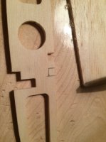
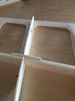
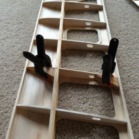
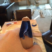
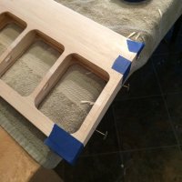
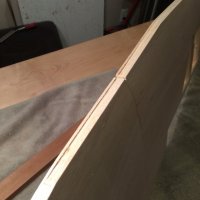
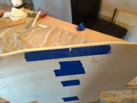
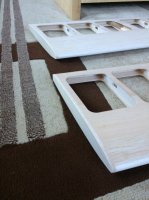
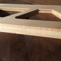
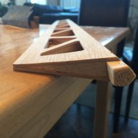
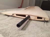
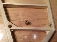
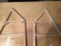
Drilled the hard points for the interplane struts and put in dowel hard points in the stabs.
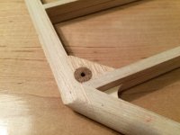
I messed up and put in balsa in the stabs where hard points should have gone using 6mm ply on each side. Put in 3/8th Oak dowels instead. I drilled the dowels out with a small bit and the plan is to strip the plastic off about 10mm of the flying wire and epoxy it into the hole using a horse needle to fill the hole. This way I can install the wires after covering and they will look clean as well as be secure.
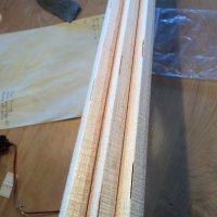
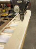
Found a little trick for drilling holes in dowels. Chuck the dowel in the drill press and clamp the bit in the vice. Worked really well this way.
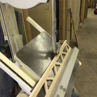
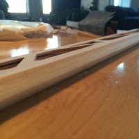
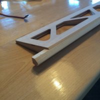
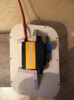
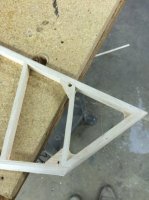
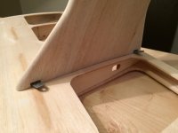
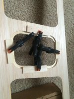
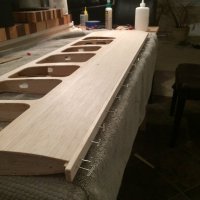
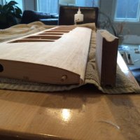
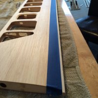
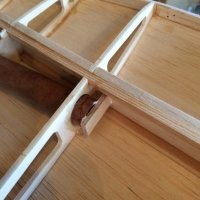
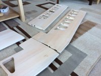
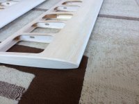
The interplane struts fitting was a relief. The blind nuts get eyed into the struts and the placement of the holes in the wing use the sheeting as a guide which is only as good as my wing build. Suppose I could have measured the holes in the sheeting from the edges of the wing. Anyway they fit!
They supply m3 bolts of just the right length for the wing thickness so I used an 1/8 bit to make a hole just slightly over sized. I drilled from the side of the wing the struts bolt on to the other side. The foam shucks leveled the wing.