• If you are new to GiantScaleNews.com, please register, introduce yourself, and make yourself at home.

    We're 1st in Giant Scale RC because we've got the best membership on the internet! Take a look around and don't forget to register to get all of the benefits of GSN membership!

    Welcome!

3D EMHW 2.15 Ultimate

Finishing up a H9 260 I've been redoing and have a dalton MEL to finish up. Got a scratch build idea kicking around, don't know if it is realistic to get done by then.
 
Finishing up a H9 260 I've been redoing and have a dalton MEL to finish up. Got a scratch build idea kicking around, don't know if it is realistic to get done by then.

Sounds like you've got your hands full!

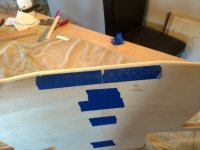
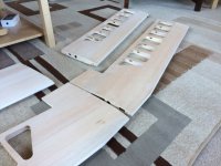
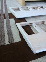
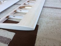
Beveled the ailerons with a bandsaw.

First step is to clean up the trailing edge of any glue or high spots as it will be the reference against the fence on the saw.

Then cut the hinge slots with the dremel with a flush cut blade.

Then worked out the angle to make the bandsaw cut to yield a 45 degree bevel. The two faces of the aileron have an 11 degree angle between them. So from the centerline from the trailing to leading edge that's a 5.5 degree angle on each side.

To get 45 degree cuts with respect to the centerline I had to subtract the 5.5 degree angle and set the saw to 39.5 degrees. Made a few small cuts sneaking up on the right setting with the fence until I was just barely connecting the cuts on either side into a sharp 90 degree edge. Then ran them all through.

Most of the hinge slots were right in the center and those that aren't can be filed in place. I cut the slots as thin as possible so each slot will need some filing and I can correct any error in the direction it needs to go.

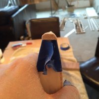
Took pictures of the saw marks the bandsaw left. Really worked well. It left a rough edge, but there was zero tear out and after a few minutes sanding with 220 paper looks perfect. I left the extra material hanging out of each end to give the sanding stick something to ride on on the edges.
 

Attachments

  • IMG_1075.JPG
    IMG_1075.JPG
    69.1 KB · Views: 489
  • IMG_1076.JPG
    IMG_1076.JPG
    74.6 KB · Views: 487
  • IMG_1077.JPG
    IMG_1077.JPG
    54.6 KB · Views: 488
  • IMG_1078.JPG
    IMG_1078.JPG
    41.8 KB · Views: 490
  • IMG_1079.JPG
    IMG_1079.JPG
    52.9 KB · Views: 493
  • IMG_1080.JPG
    IMG_1080.JPG
    48 KB · Views: 488
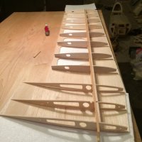
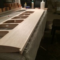
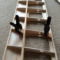
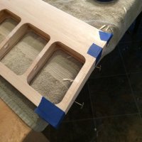
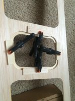
Progress on the wings. I used the foam shucks weighted down to glue the sheeting to the ribs/spars one side at a time. It isn't super clear from the way they label the wood size in the pictures, but all the wings build the same. On the sheeting goes 15x6 for the trailing edge and 10x5 for the leading edge. Then once the sheeting is glued on each side, the leading edge is capped with 15x6 which partially sanded away to give the leading edge curve.

Learning as I go, figured out the wings go together really nicely if all the angles are carefully sanded into the spars and ribs. Sand a slight angle into the leading edge spar and trailing edge spar so they mesh with the ribs and stand at 90 degrees with the center of the wing. After just enough sanding to get the angle everything seems to fit perfect. The sheeting is pre-cut and the holes make it easy to see the proper angles.

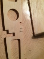
The second rib in from the root on the top wing has a misplaced relief cut for the spar. No big deal to cut a new one in the right spot.

I used Titebond III for a longer open time and first glued and pinned the leading/trailing edge spars then the middle spars and ribs working from one end to another. Then weight. Worked well once I started sanding angles in everything carefully.

Used epoxy on the wing tubes and wood glue on anti-rotation points and caps for the end of the wing tubes.

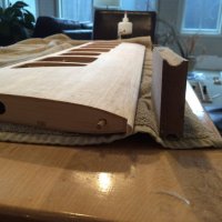
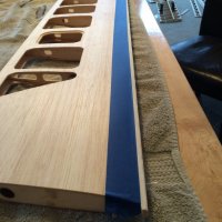
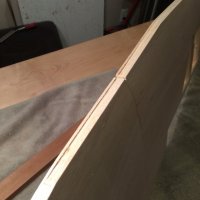
Once each side of the sheeting was on, the leading and trailing edges were carefully sanded flat and the 15x6 stick was glued to the leading edge. I made a little sanding jig with two small round nose router bits. One side was a little bigger than the other and put 120 grit in the larger and 220 in the smaller. I sanded with the large side until the flat portion disappeared then a little more with the tighter 220 side. This got it really close and I could finish with a sanding stick and paper in hand. The top wing has a flat portion in the middle before the wings begin sweeping back so I always sanded this portion and the middle trailing edge with the wings attached together.

6mm thick balsa cap ribs were glued on after sanding the ends nice and flat.
 

Attachments

  • IMG_1054.JPG
    IMG_1054.JPG
    57.7 KB · Views: 462
  • IMG_1060.JPG
    IMG_1060.JPG
    47.7 KB · Views: 496
  • IMG_1062.JPG
    IMG_1062.JPG
    36.9 KB · Views: 504
  • IMG_1070.JPG
    IMG_1070.JPG
    61 KB · Views: 484
  • IMG_1072.JPG
    IMG_1072.JPG
    58.6 KB · Views: 498
  • IMG_1083.JPG
    IMG_1083.JPG
    48.3 KB · Views: 485
  • IMG_1086.JPG
    IMG_1086.JPG
    55.5 KB · Views: 473
  • IMG_1090.JPG
    IMG_1090.JPG
    89.7 KB · Views: 489
  • IMG_1091.JPG
    IMG_1091.JPG
    57.6 KB · Views: 467
  • IMG_1092.JPG
    IMG_1092.JPG
    71.4 KB · Views: 461
  • IMG_1093.JPG
    IMG_1093.JPG
    49.8 KB · Views: 481
  • IMG_1095.JPG
    IMG_1095.JPG
    62.3 KB · Views: 469
  • IMG_1096.JPG
    IMG_1096.JPG
    62.6 KB · Views: 467
  • IMG_1098.JPG
    IMG_1098.JPG
    42.8 KB · Views: 464
  • IMG_1102.JPG
    IMG_1102.JPG
    68.6 KB · Views: 485
  • IMG_1104.JPG
    IMG_1104.JPG
    93 KB · Views: 491
  • IMG_1105.JPG
    IMG_1105.JPG
    59.5 KB · Views: 470
  • IMG_1106.JPG
    IMG_1106.JPG
    90.9 KB · Views: 475
Haha, thanks!

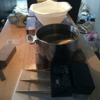
I can tell you a wing won't make a pot boil even if you watch it. I tried.

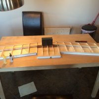
Did a quick/rough wing area calculation and got 2318 in^2
 
Thanks Terry!

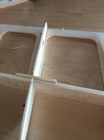
The top wing halves each have a liteply doubler that fits in between them so they meet together over the center strut. I mounted up the center strut to glue these on so I could be sure they weren't interfering with the strut. Once glued on I've been putting the wings together and taking them apart sanding a little each time to get a tight fit.

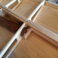
Couple pictures of the aileron servo mounts. Did them very similar to how emhw showed in the included pictures.
 

Attachments

  • IMG_1107.JPG
    IMG_1107.JPG
    98.8 KB · Views: 497
  • IMG_1108.JPG
    IMG_1108.JPG
    35.2 KB · Views: 476
  • IMG_1109.JPG
    IMG_1109.JPG
    40.9 KB · Views: 448
  • IMG_1114.JPG
    IMG_1114.JPG
    87.2 KB · Views: 481
Drilled the hard points for the interplane struts and put in dowel hard points in the stabs.

I messed up and put in balsa in the stabs where hard points should have gone using 6mm ply on each side. Put in 3/8th Oak dowels instead. I drilled the dowels out with a small bit and the plan is to strip the plastic off about 10mm of the flying wire and epoxy it into the hole using a horse needle to fill the hole. This way I can install the wires after covering and they will look clean as well as be secure.

Found a little trick for drilling holes in dowels. Chuck the dowel in the drill press and clamp the bit in the vice. Worked really well this way.

The interplane struts fitting was a relief. The blind nuts get eyed into the struts and the placement of the holes in the wing use the sheeting as a guide which is only as good as my wing build. Suppose I could have measured the holes in the sheeting from the edges of the wing. Anyway they fit!

They supply m3 bolts of just the right length for the wing thickness so I used an 1/8 bit to make a hole just slightly over sized. I drilled from the side of the wing the struts bolt on to the other side. The foam shucks leveled the wing.
 

Attachments

  • IMG_1115.JPG
    IMG_1115.JPG
    58.8 KB · Views: 453
  • IMG_1116.JPG
    IMG_1116.JPG
    56.2 KB · Views: 447
  • IMG_1117.JPG
    IMG_1117.JPG
    49 KB · Views: 472
  • IMG_1118.JPG
    IMG_1118.JPG
    59.6 KB · Views: 448
  • IMG_1119.JPG
    IMG_1119.JPG
    82 KB · Views: 457
  • IMG_1120.JPG
    IMG_1120.JPG
    73.4 KB · Views: 461
  • IMG_1121.JPG
    IMG_1121.JPG
    73.2 KB · Views: 492

Jetpainter

640cc Uber Pimp
Drilled the hard points for the interplane struts and put in dowel hard points in the stabs.

I messed up and put in balsa in the stabs where hard points should have gone using 6mm ply on each side. Put in 3/8th Oak dowels instead. I drilled the dowels out with a small bit and the plan is to strip the plastic off about 10mm of the flying wire and epoxy it into the hole using a horse needle to fill the hole. This way I can install the wires after covering and they will look clean as well as be secure.

Found a little trick for drilling holes in dowels. Chuck the dowel in the drill press and clamp the bit in the vice. Worked really well this way.

The interplane struts fitting was a relief. The blind nuts get eyed into the struts and the placement of the holes in the wing use the sheeting as a guide which is only as good as my wing build. Suppose I could have measured the holes in the sheeting from the edges of the wing. Anyway they fit!

They supply m3 bolts of just the right length for the wing thickness so I used an 1/8 bit to make a hole just slightly over sized. I drilled from the side of the wing the struts bolt on to the other side. The foam shucks leveled the wing.


Nice work!
 
Top