• If you are new to GiantScaleNews.com, please register, introduce yourself, and make yourself at home.

    We're 1st in Giant Scale RC because we've got the best membership on the internet! Take a look around and don't forget to register to get all of the benefits of GSN membership!

    Welcome!
  • Unless you are a paid advertiser NO more posting advertisement in the individual vendor forums. You may post in the Manufacturer's Announcements section only but only ONCE a month unless your a paid advertiser.

Redwing RC 76" MXS-R

TimP

GSN Sponsor Tier 1
Yes, the lower cowl attachments are being worked on. We have a new solution being applied to all new designs. It doesn't make sense to add bolts that are hidden if you have to cut a hole to access easily. You can get them with a LONG all wrench (handle), but the new design will be much better.

glad you got the cowl spaced out soon. You could pop the cowl ring off, but if a couple washers got it that close it's not worth it. We listen carefully and try to improve with EVERY batch.
 

Drew

70cc twin V2
Installed ignition last night....nothing to special here

SAM_0418.JPG

SAM_0419.JPG

SAM_0420.JPG
 

Drew

70cc twin V2
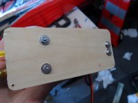
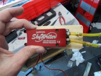
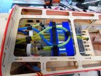
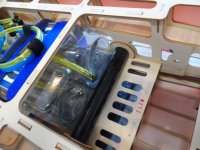
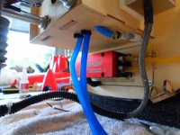
Got the smoke system installed yesterday. Doing a little research I'm finding that everyone's CG on this plane requires there batteries around the tank area, which wont work for this plane with 2 tanks. So I put the smoke pump up front hoping this will allow me to put the Lipos behind the wing tube.


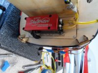
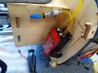
The fuse has a removable canister tunnel plate, so I mounted the pump to it. Pump has 2 lines, one feeds right from tank threw a filter into the pump, then pump feeds oil out threw a one way valve into the smoke muffler. The muffler then heats the oil and creates smoke. Very simple to set up really.

SAM_0421.JPG

SAM_0422.JPG

SAM_0425.JPG

SAM_0426.JPG

Set up the lines for the tank.

SAM_0427.JPG

Wont be using smoke all the time so ran the fill from the "T" to the back of the tank area, no needed fuel dot.

SAM_0428.JPG

Vent lines for both tanks ran.

SAM_0430.JPG

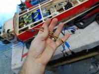
Labeled wiring for pump power, pump signal, throttle servo, and also still need to run ignition power. Lots of wiring in this bird. :megaroll:

SAM_0432.JPG
 

Drew

70cc twin V2
Last thing I started last night was setting up the rudder. I epoxied in the control horns on both sides..... More to come......

SAM_0433.JPG
 

SnowDog

Moderator
Got the smoke system installed yesterday. Doing a little research I'm finding that everyone's CG on this plane requires there batteries around the tank area, which wont work for this plane with 2 tanks. So I put the smoke pump up front hoping this will allow me to put the Lipos behind the wing tube.

The fuse has a removable canister tunnel plate, so I mounted the pump to it. Pump has 2 lines, one feeds right from tank threw a filter into the pump, then pump feeds oil out threw a one way valve into the smoke muffler. The muffler then heats the oil and creates smoke. Very simple to set up really.

View attachment 18764

ALthough this looks like a handy forward position to mount the smoke pump, I'm asking myself the question now: how will you be providing exit venting for airflow?

You've got the air intake holes in the front of the cowl, but where will that air exit the plane?

On my 30cc birds and my 50cc bird, there is a vent plate on the bottom of the cannister tunnel which can be used for exit air vents...but if you've got the cannister tunnel blocked with the smoke pump, that won't work for you...

perhaps mounting the smoke pump to the bottom of the motor box would work beter? Then you could leave the cannister opening off and provide exit air venting in the normal manner?
 
Last edited by a moderator:

gyro

GSN Contributor
ALthough this looks like a handy forward position to mount the smoke pump, I'm asking myself the question now: how will you be providing exit venting for airflow?

You've got the air intake holes in the front of the cowl, but where will that air exit the plane?

On my 30cc birds and my 50cc bird, there is a vent plate on the bottom of the cannister tunnel which can be used for exit air vents...but if you've got the cannister tunnel blocked with the smoke pump, that won't work for you...

perhaps mounting the smoke pump to the bottom of the motor box would work beter? Then you could leave the cannister opening off and provide exit air venting in the normal manner?
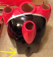
In really like the current mounting location, especially since the cowl design itself has a cooling vent built at the aft/bottom side.

Notice it in this picture how the bottom protrudes and has a hump? It's open to the rear for airflow to move through and out:
ImageUploadedByTapatalk1383765252.946199.jpg
 

Drew

70cc twin V2
ALthough this looks like a handy forward position to mount the smoke pump, I'm asking myself the question now: how will you be providing exit venting for airflow?

You've got the air intake holes in the front of the cowl, but where will that air exit the plane?

On my 30cc birds and my 50cc bird, there is a vent plate on the bottom of the cannister tunnel which can be used for exit air vents...but if you've got the cannister tunnel blocked with the smoke pump, that won't work for you...

perhaps mounting the smoke pump to the bottom of the motor box would work beter? Then you could leave the cannister opening off and provide exit air venting in the normal manner?
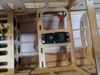
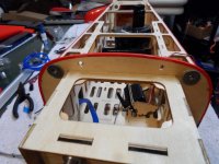
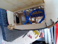
Well, the air flow threw this opening would not work since the inner fuse has holes everywhere as well as back towards the end of the tunnel. This will then create to much airflow threw out the inside of the fuse and make the flow worse. As Gary mentioned, the cowl has a built in air exit. There is really not much air coming in, there for not much needed to go out. I'm planning on a few extra holes in the back of the cowl just in case. Not knocking this airframe, but if you were to run a canister in this plane, lots of changes would need to be made. Look at the pics below to show you how open the canister tunnel is. You would have to add wood to block these in order to get proper flow.

Lots of holes for the air to exit.

SAM_0403.JPG

SAM_0423.JPG

Look at this pic in front of the rudder servo, you can see the end of the tunnel is open for air to enter the fuse.

SAM_0398.JPG
 
Last edited by a moderator:

SnowDog

Moderator
In really like the current mounting location, especially since the cowl design itself has a cooling vent built at the aft/bottom side.

Notice it in this picture how the bottom protrudes and has a hump? It's open to the rear for airflow to move through and out:
View attachment 18787

I see what you are talking about...I'd like to see a bottom and side view pic of the cowl attached to the airframe.

It should be enough exit area, I suppose.
 
Top